Song of the Sea UE5 Project Breakdown
- The Idea
- Unreal Engine Layered Material
- Custom Shading Model: CTCel
- The Sea
- Saoirse
- Foliage
- Vertex Animated Seagulls
The Idea
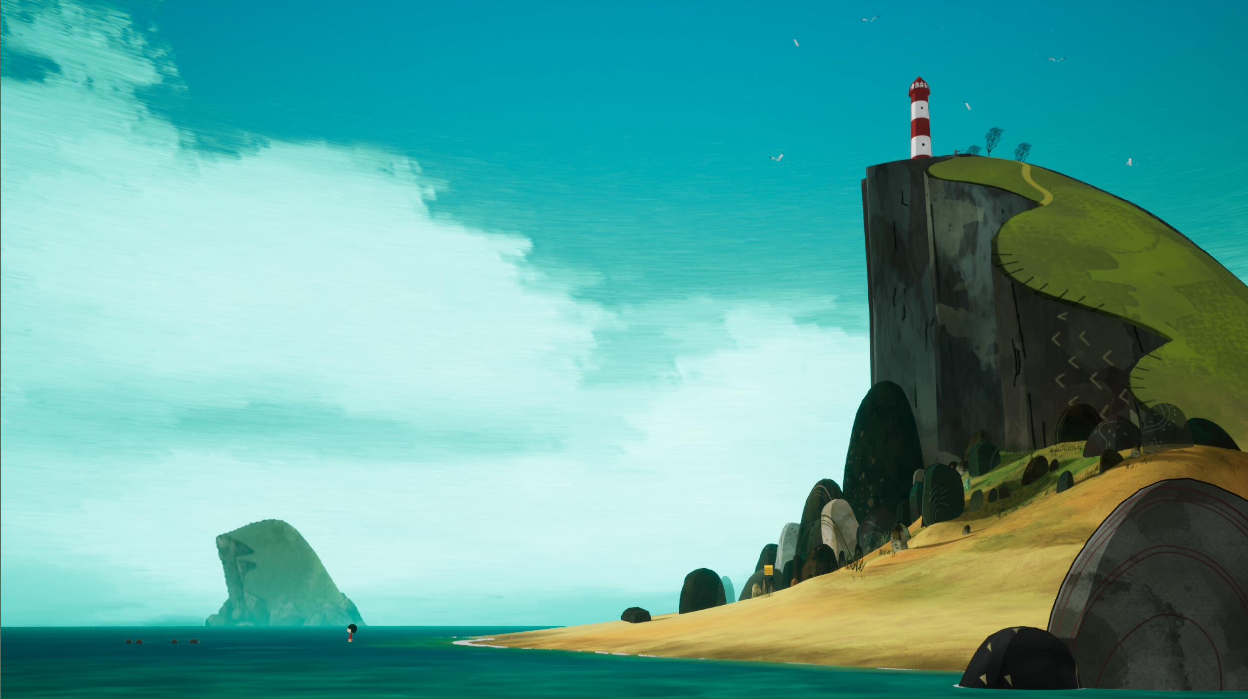
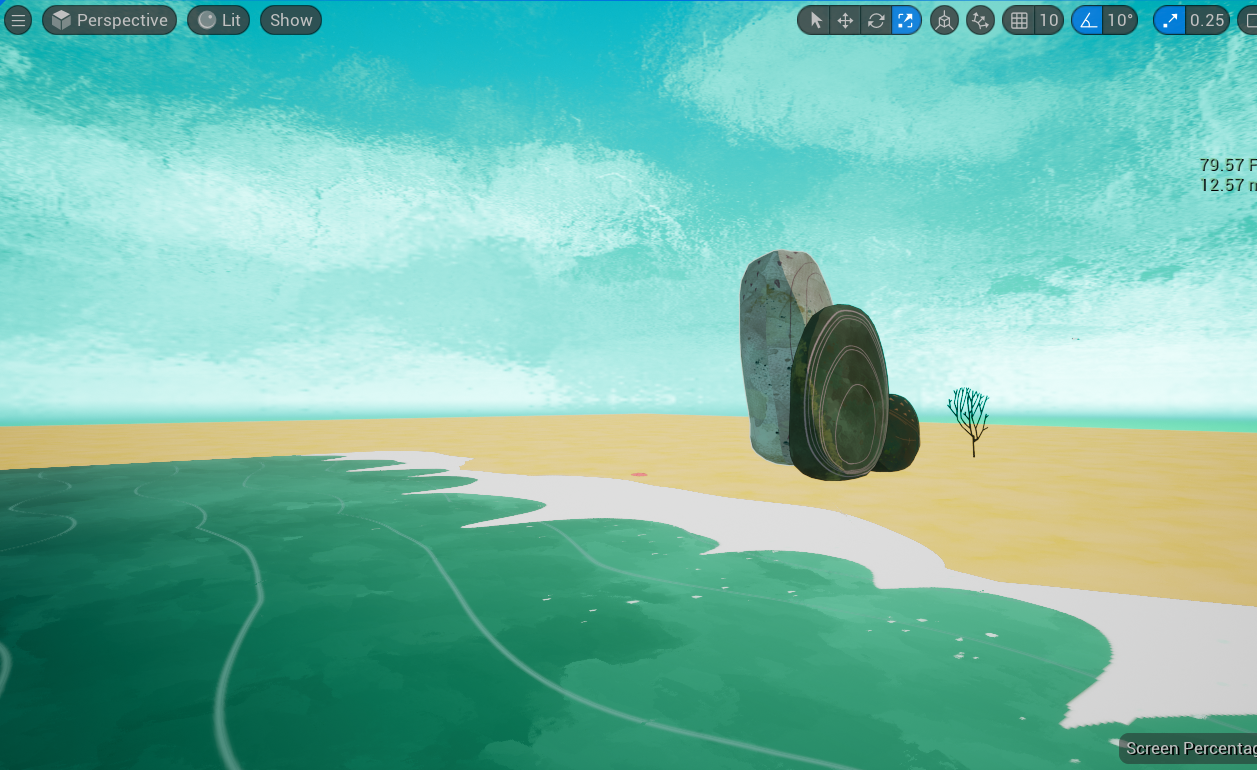
:ocean:Song of the Sea:ocean: is one of my favorite animation films. The special art style with watercolor is so interesting and appealing, which really motivates me to make a 3D scene to build the iconic landscape of the film in the game engine.
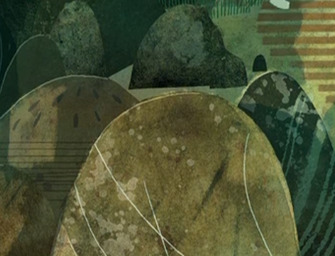
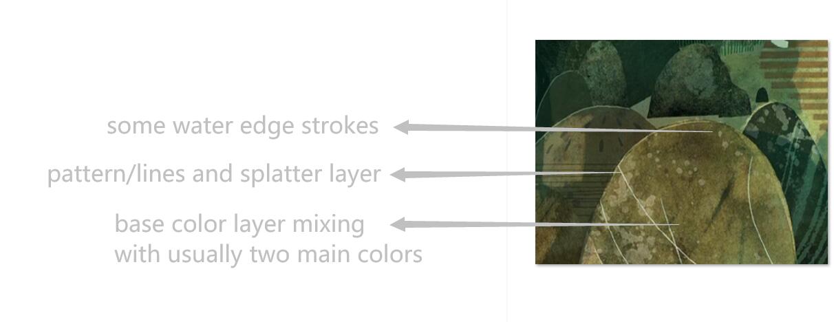
Firstly I downloaded the movie, watched it again, took screenshots and studied the details of the style. Basically, it is flat, overlaying multiple layers of colour, strokes, splatters, dots, and mixing randomly.
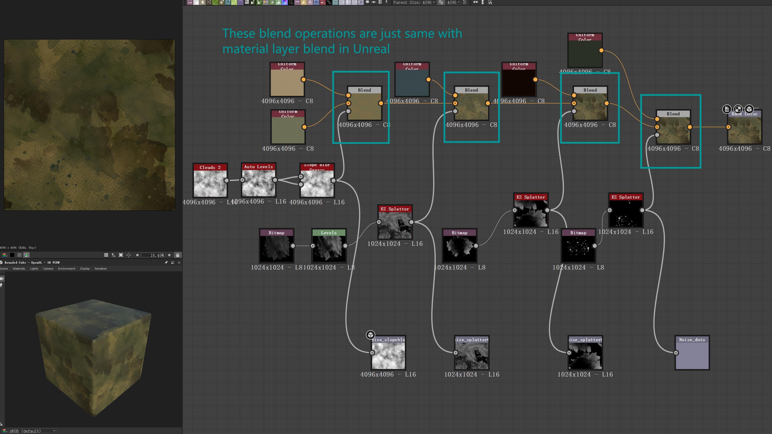
I started to figure out how to make the handpainted watercolour effect of the texture, that dominates the overall impression. So here we go, Substance Designer! I did some research on stylizing textures, and videos from Stylized Station really inspired me and were helpful. The key step is slope blur, which really gives a very watercolour/guache feeling. Slope blur is available in both SD and SP, and I chose SD to explore the style since it has a clearer structure.
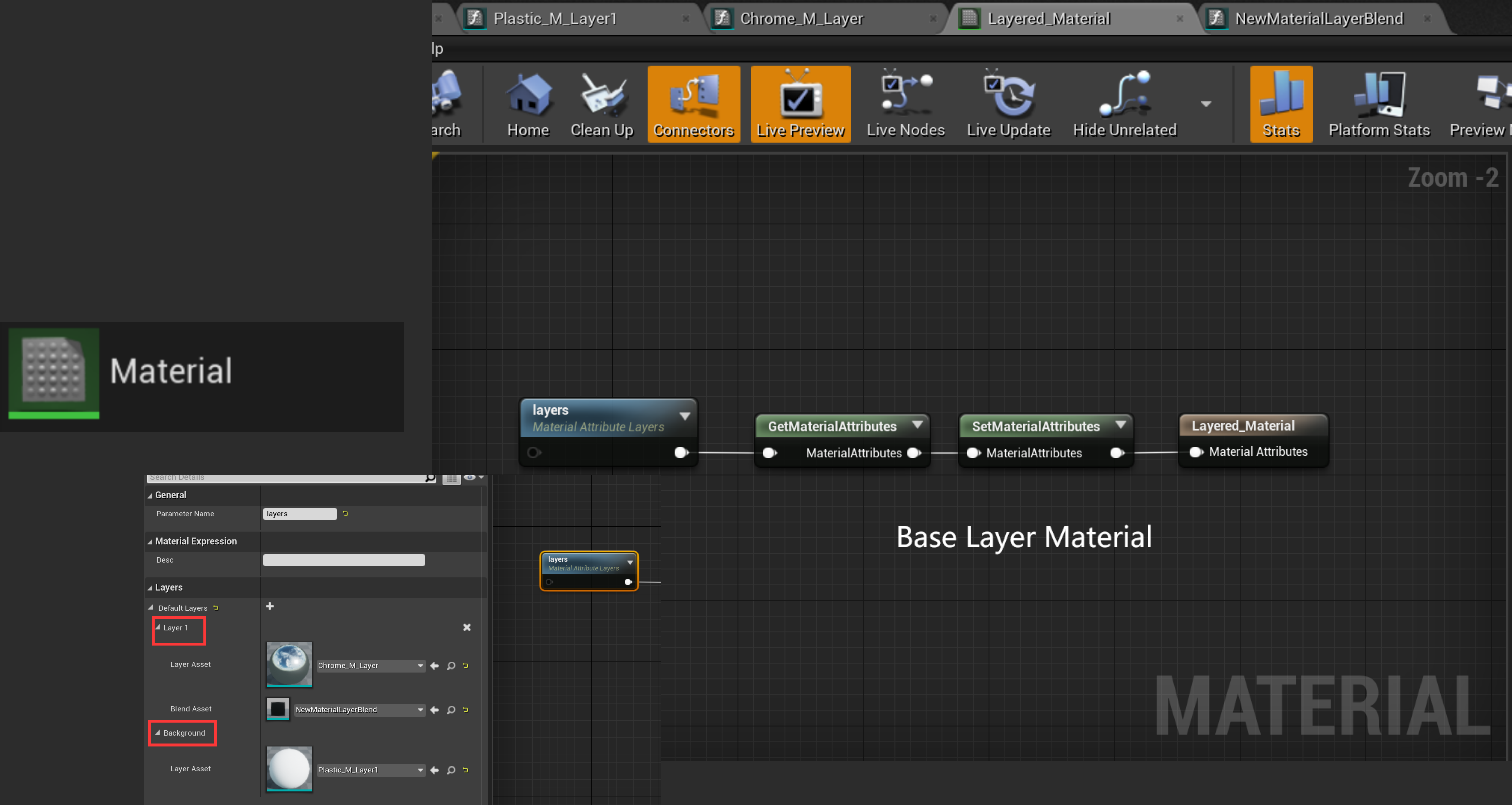
At the first, I planned to make the whole texture pipeline in SD, but during exploring in SD, I found it was better to mix in the engine directly. I had the experience of using UE layered material workflow for a project to make landscapes, and that approach is very flexible and efficient, which is perfect for this layering artistic style.
Unreal Engine Layered Material
Structure
The structure of Unreal Engine layered material is like, not lerp the effect in a base material all together but to mix it in the material instance with their provided UI, which is clear, light, and very flexible. It’s like you drawing in Photoshop, with all the image layers.
Material Layer Blend asset.
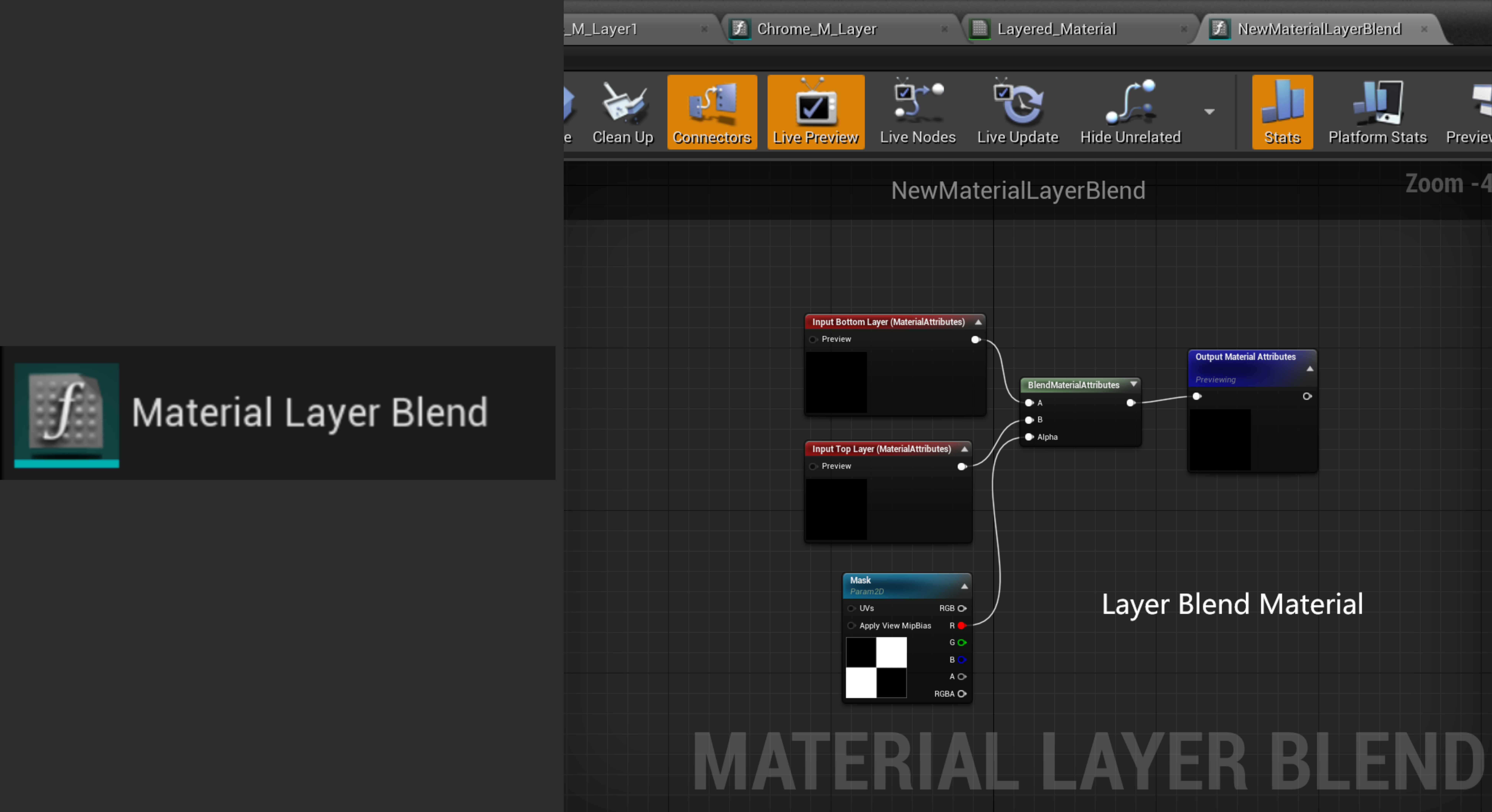
So this asset decides how your current layer and layer below blend together, for example, the checker map here I use, will blend the current layer in the white area, and layer/layers underneath it into the black area.Material Layer.
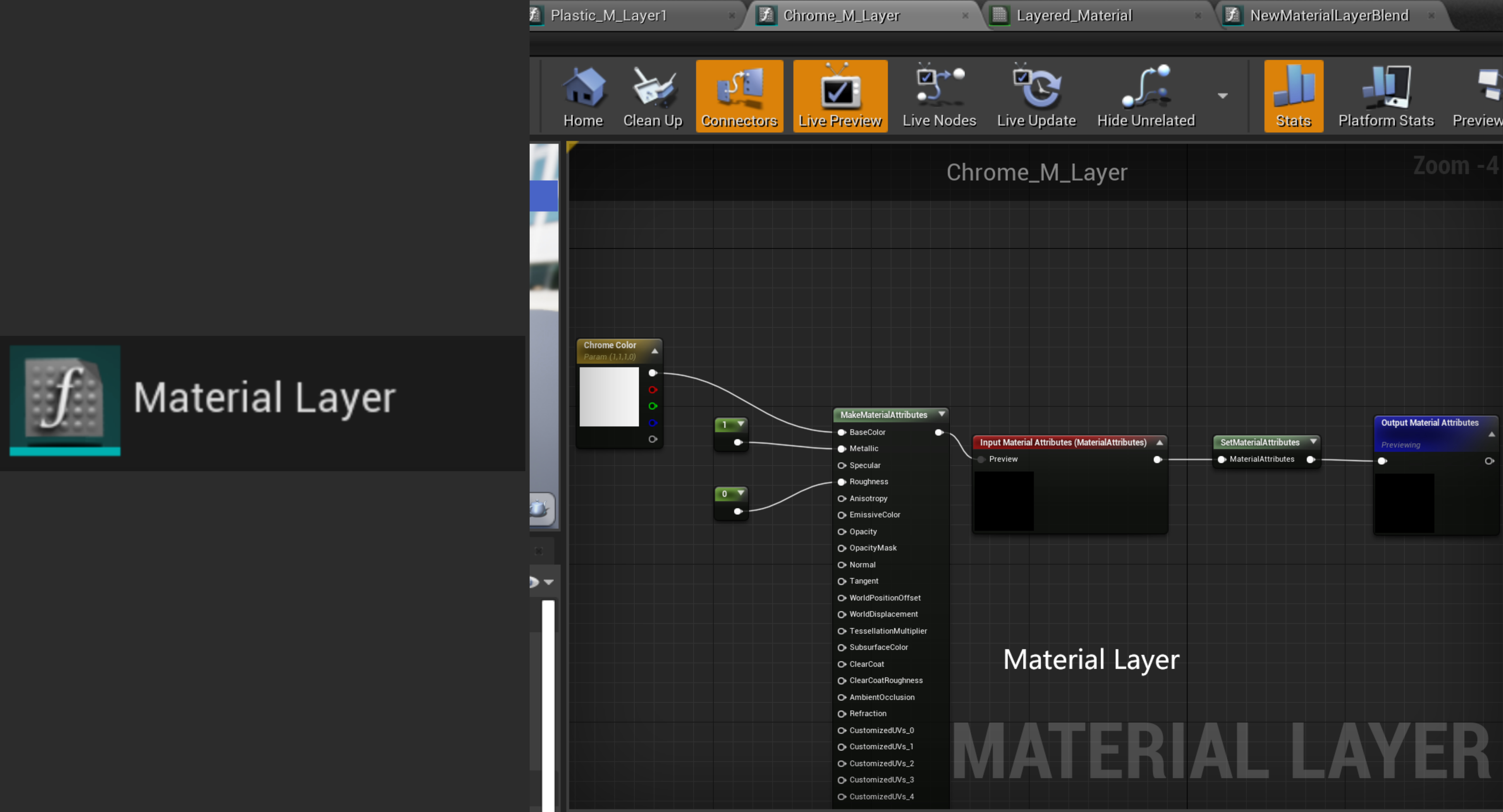
Material layer asset is where you write your features and the attributes you want to output.
Utilize
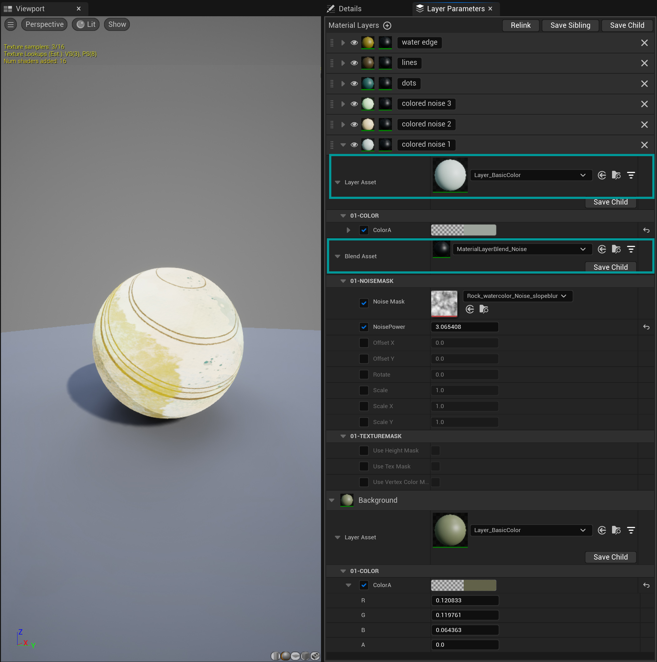
Take, one of my stone material instance for example, you can see there are 7 layers, each one in charge of different colors and patterns. The material layer blend asset I used most for this project is:

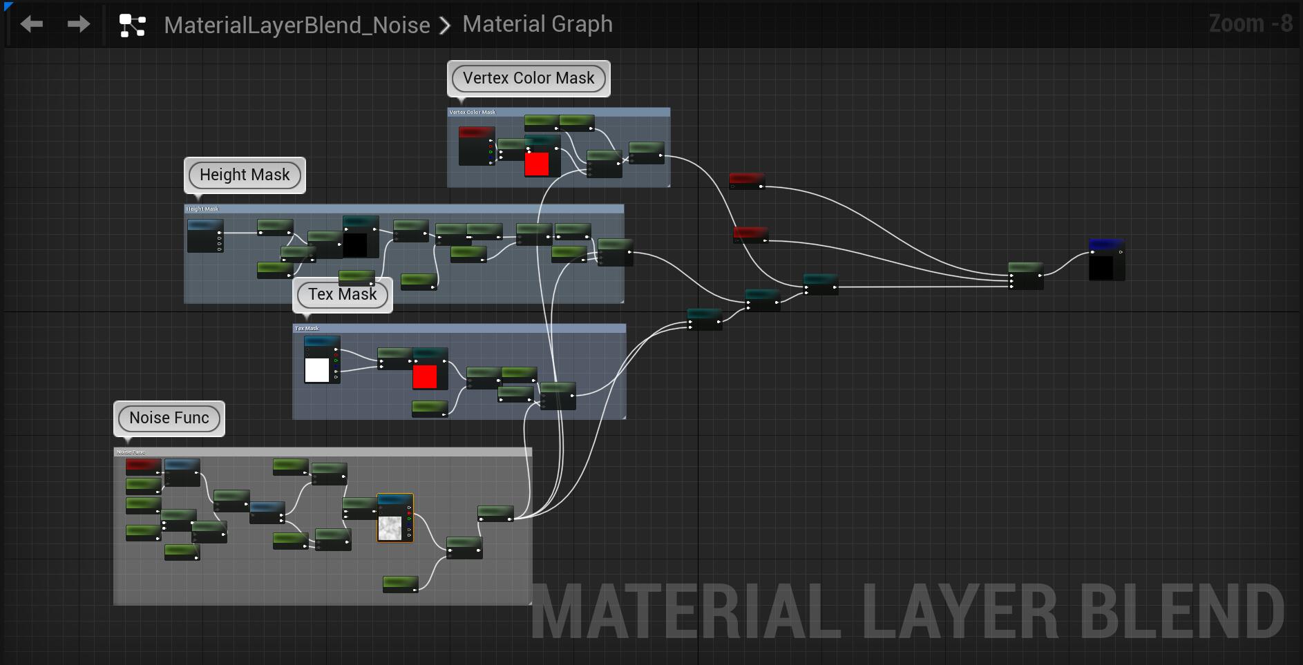
which using one noise texture as the main lerp value and with three additional mask modes, almost cover all ways of masking:
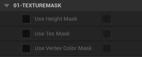
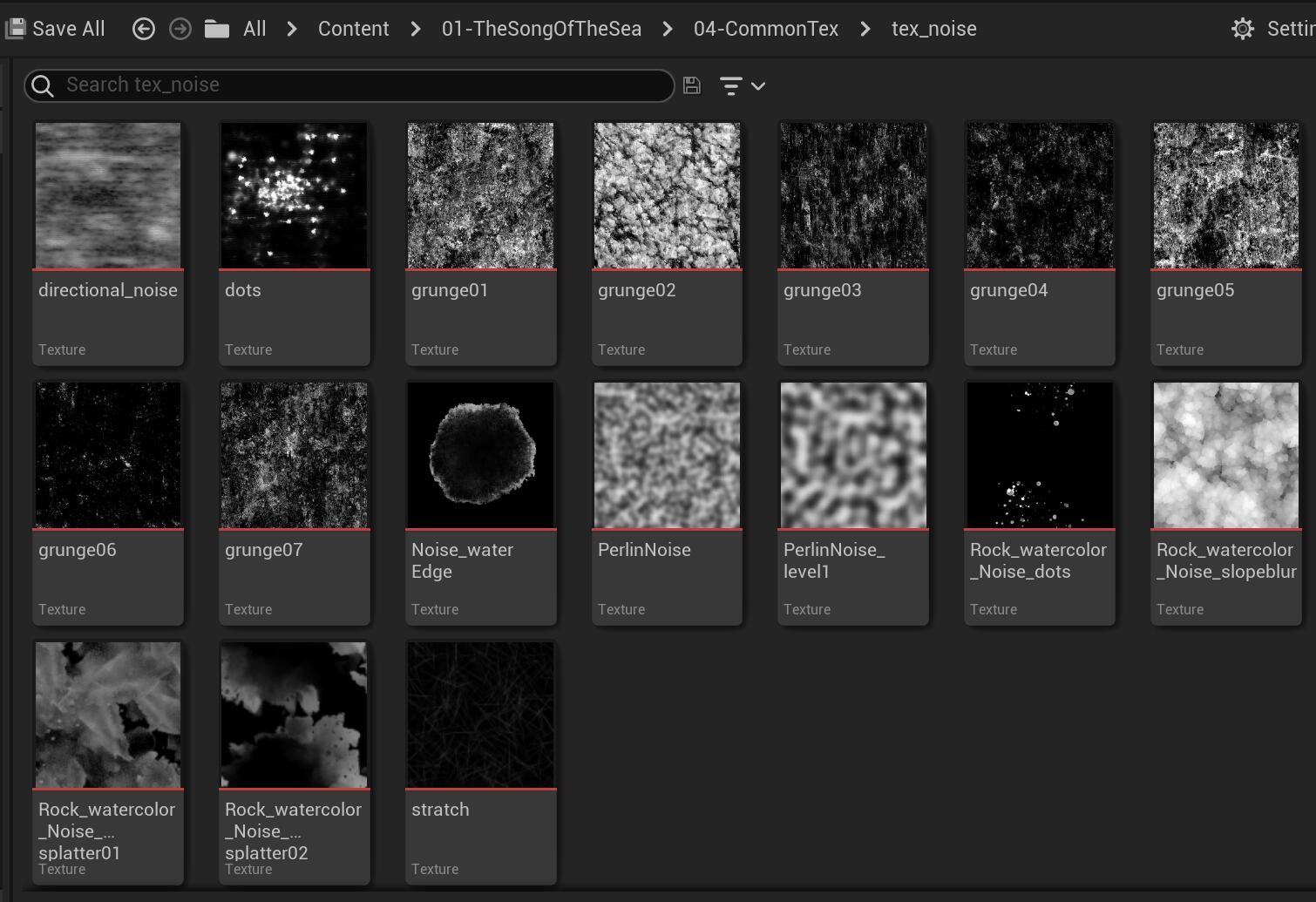
And these are my noise textures using to create those handpainted style materials, except the grunge images, others were created and exported from Substance Designer.
Below are blend assets and layer assets I created for this project:
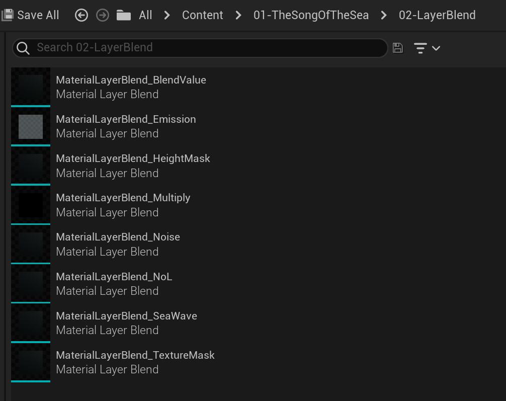
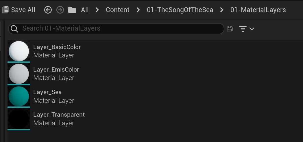
Flexibility and Consistency
For me, specifically in this project, the layered material pipeline provides more pros. The most beneficial part is flexibility and meanwhile consistency. As it allows me to layer dozens of effects with complete material tuning control, I can skip the bulky assets importing steps, and preview right away in the engine viewport. In the past studio experience, especially in two NPR projects that we build specialized shading models, consistency is always the most painful thing in the production for either character or environment artists. I had written shaders across platforms from game engines (Unity or UE), Substance Painter, Maya, 3DMax, and Marmoset, to allow artists to contain consistency on any DCC software, and that costs time to keep updating all together everytime once modification happens.
Unfortunately, More samplers
Obviously, stacking in real-time will produce more samples compared to baking texture all together. In Gears of War 4: Creating a Layered Material System for 60fps, the team developed a material cooker that was implemented with the engine material layer system, allowing to cook the stacking material down to its simplest form. Well, what if when we just make a small project and don’t really need an extremly efficient run-time performance? Unreal provided the Texture Share feature.
Texture Share
Texture Share efficiently sends and receives GPU data between processes by bypassing the CPU and its expensive memory-copy operation by keeping the data stored in GPU memory.
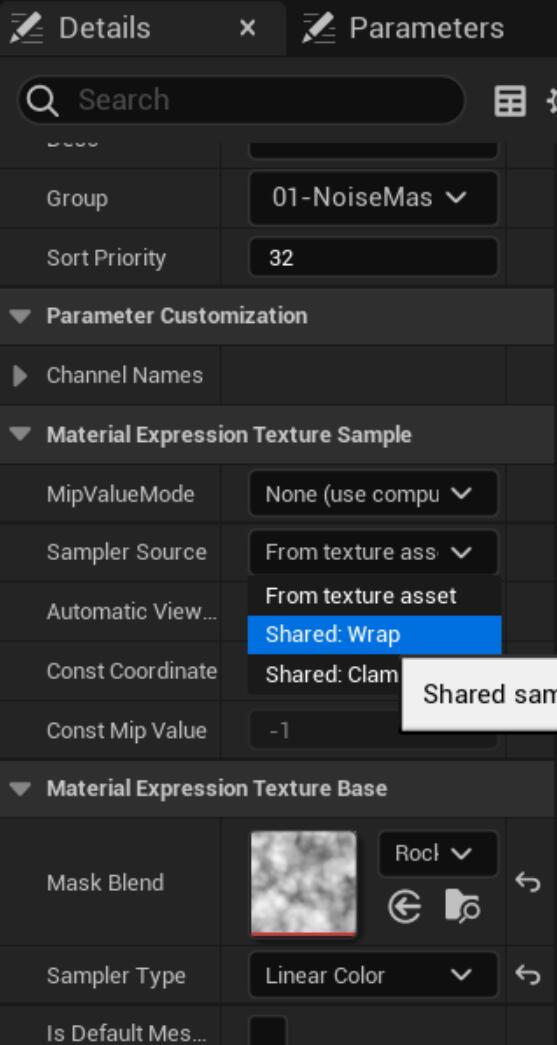
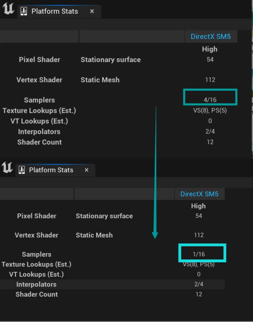
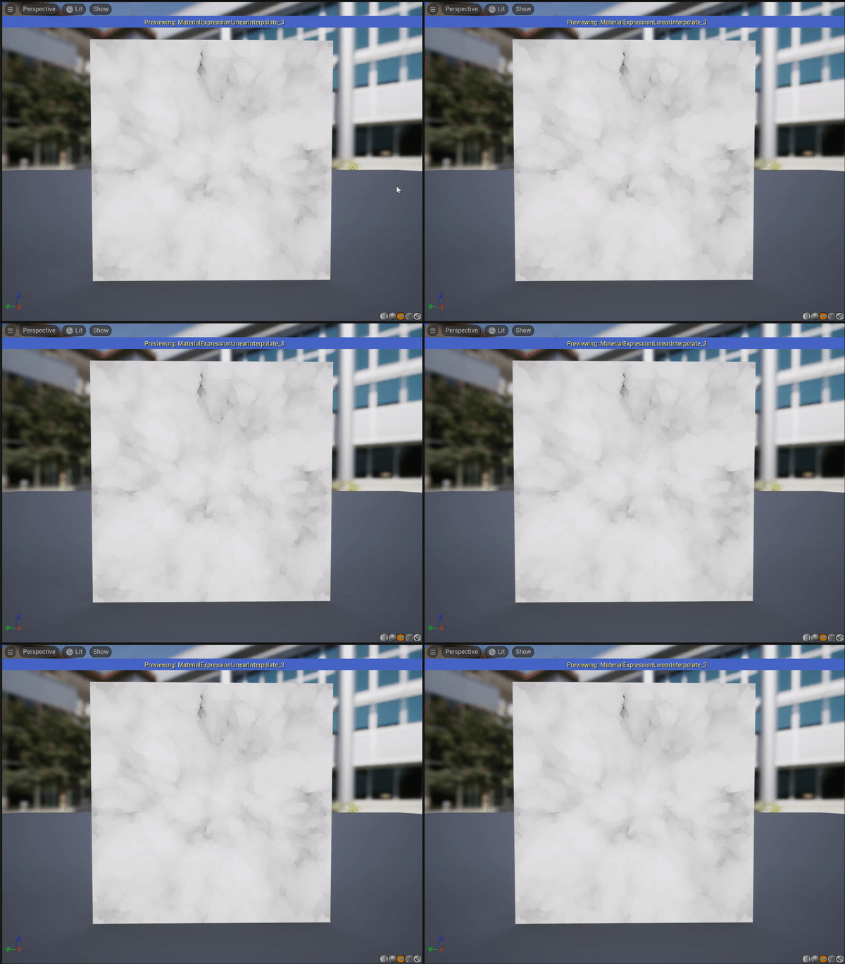
The below image shows after I turn on the shared texture sampler, a stacking material that 4 layers using the same noise mask, whose sampler reduces from 4 to 1.
Shader Complexity
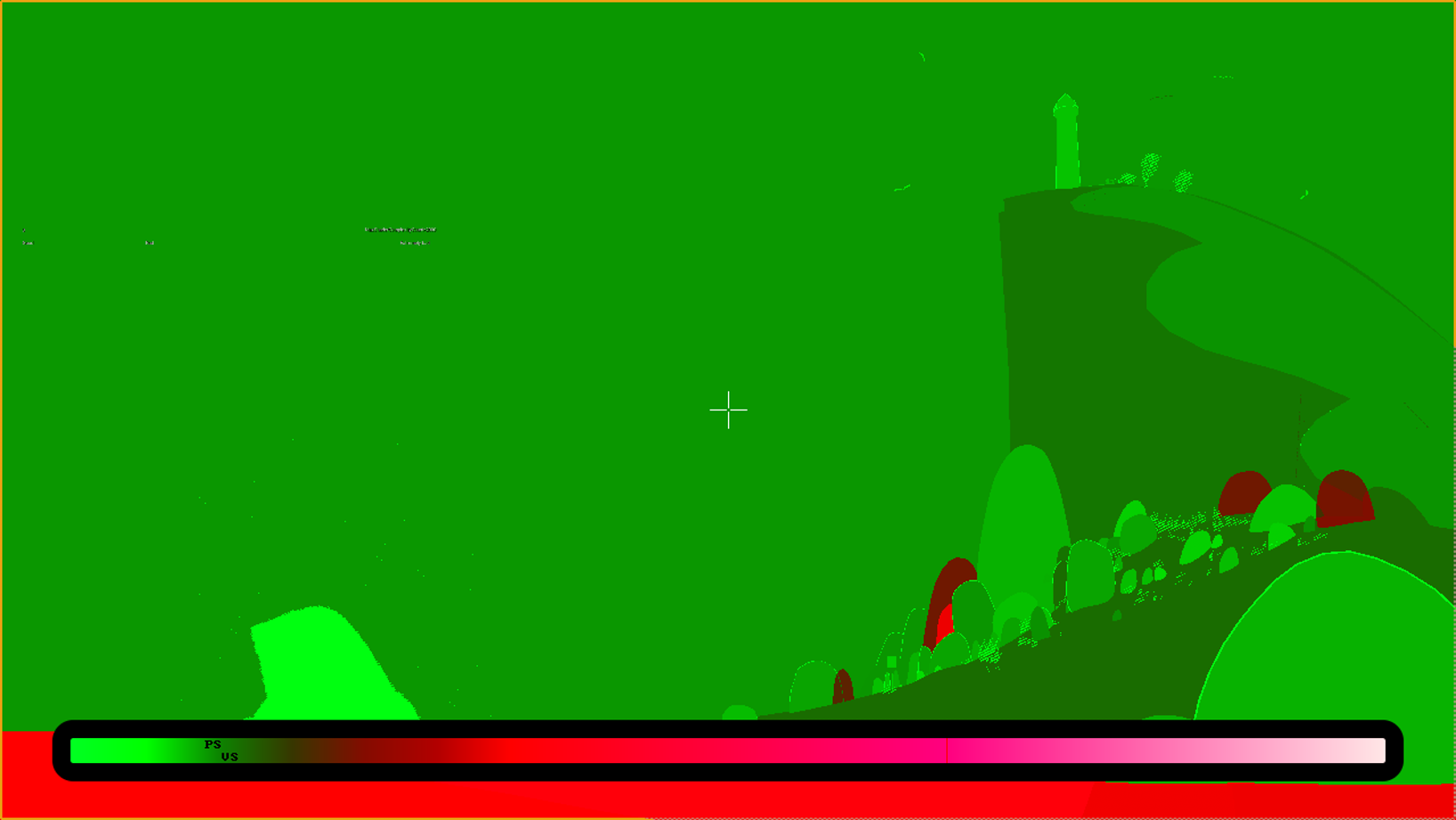
Basically, all the red objects are with a transparent material, others variate based on the number of layers, for instance, materials of the cliff and the sand dune piled 8 to 9 layers, and shown darker green here, but generally within the ‘good’ scope.
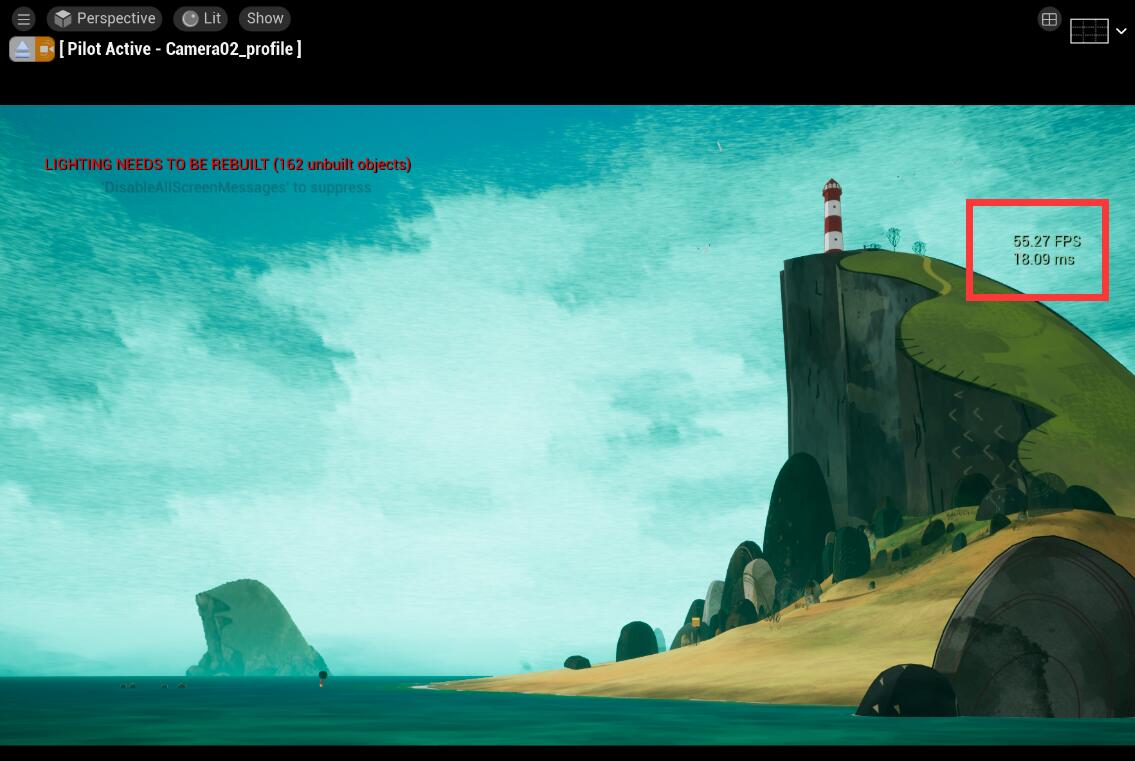
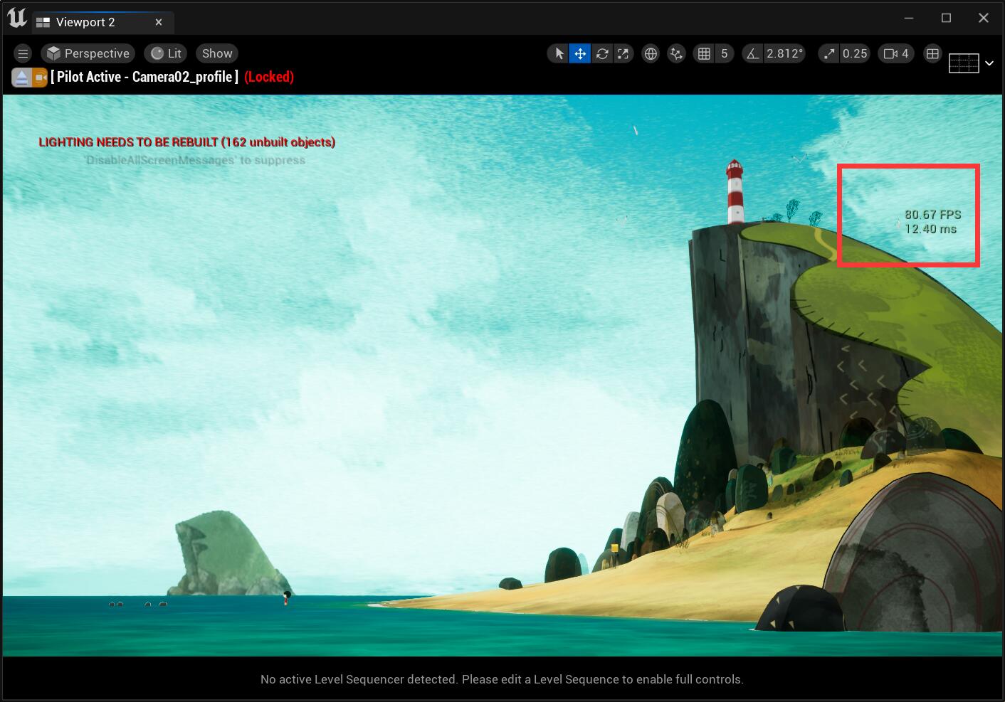
In the viewport and the static camera view, if I open the exponential height fog, I was getting 55~45 FPS overall, once close it, it rises immediately to about 80 FPS.
Custom Shading Model: CTCel
If it’s beyond the scope…
I have to say the most painful experience with Unreal Engine is you cannot add a custom lighting model or custom shader like Unity does, I personally think that is very restricted for technical artists.:face_with_head_bandage:
I’ve done that in Unreal Engine 4 in the previous studio, I guessed it won’t be very differerent in UE5
At first, I was hesitant to create a custom shading model or not. I used a blend layer that grabs light direction from the source code into a custom node to make a NOL mask:
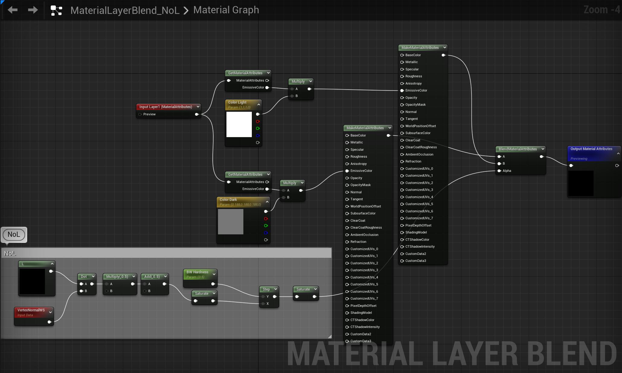
you can find these short code in BasePassPixelShader.usf and use it in custom code node to get the directional light direction and light color with an unlit master material.
ResolvedView.DirectionalLightDirection.xyz
ResolvedView.DirectionalLightColor.rgb
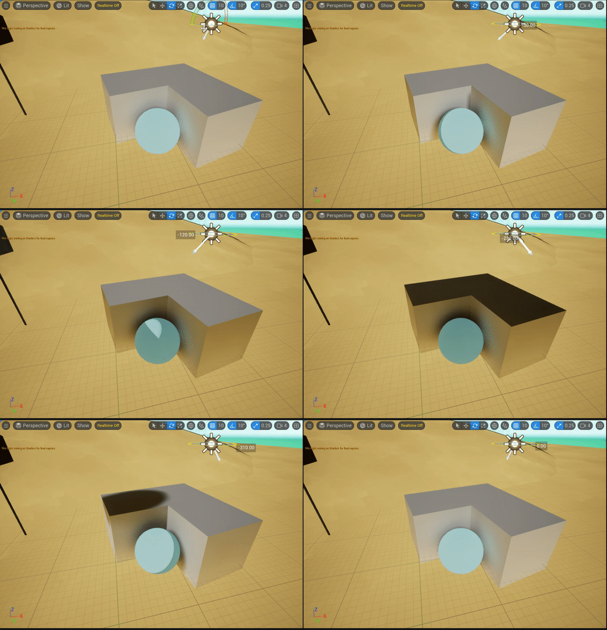
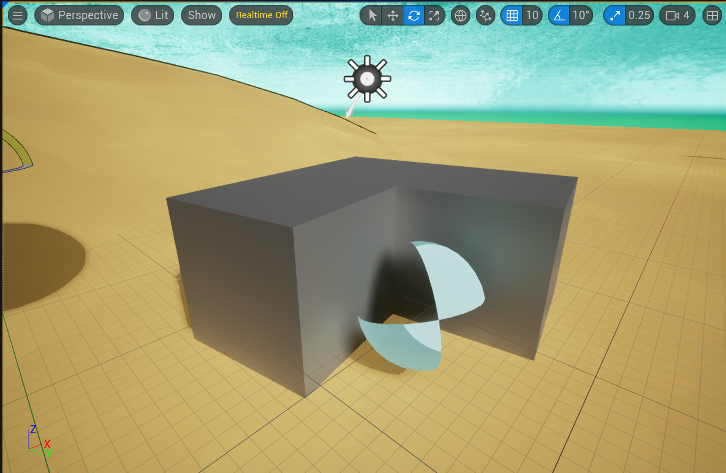
However, in this way the object is not able to cast a shadow, like the image below, you see there is no shadow on the ground:
Thus, I need to add a shading model…:triumph:
C++ files
Below is the list of C++ and header files that you need to revise:
EngineTypes.h MaterialShader.cpp HLSLMaterialTranslator.cpp Material.cpp MaterialShared.cpp ShaderMaterial.h ShaderMaterialDerivedHelpers.cpp ShaderGenerationUtil.cpp
Read this article by Matt Hoffman, and you will get 90% done with the new shading model: Unreal Engine 4 Rendering Part 6: Adding a new Shading Model
However, in UE5, one file need to be revised additionally: ShaderGenerationUtil.cpp
You need to change three places in this file:
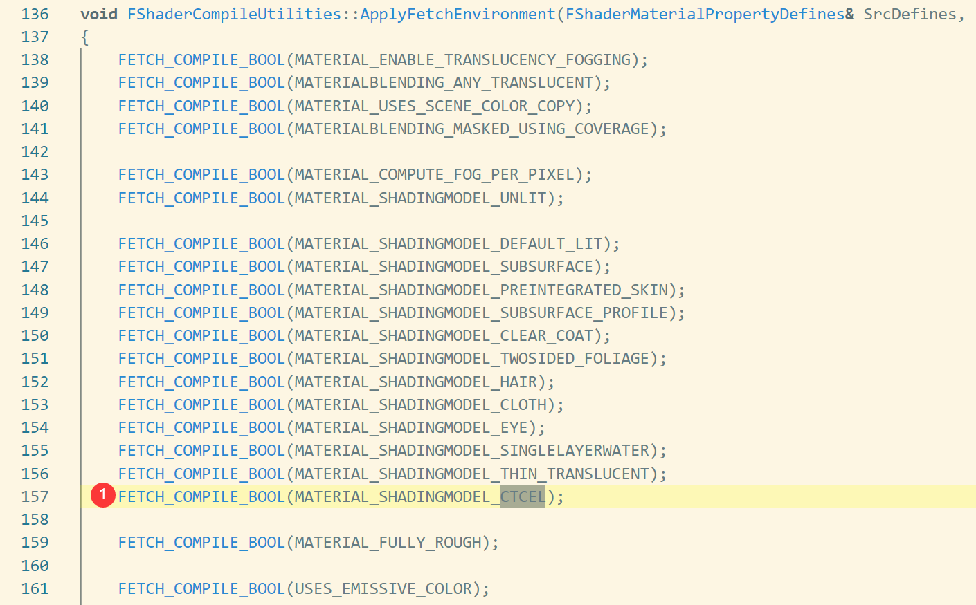
.png)
.png)
Otherwise, after build, you will see your shading model and able to choose, but it just showing solid black.
Shader files
Below is the list of shader files that you need to modify:
ShadingCommon.ush Definitions.usf BasePassCommon.ush DeferredShadingCommon.ush ShadingModelsMaterial.ush ShadingModels.ush DeferredLightingCommon.ush
You can just follow Matt Hoffman’s article to write the shader files. While for me, I add some additional codes to allow my new shading model available for the Masked blend mode as I need it for my foliages and some parts of characters.
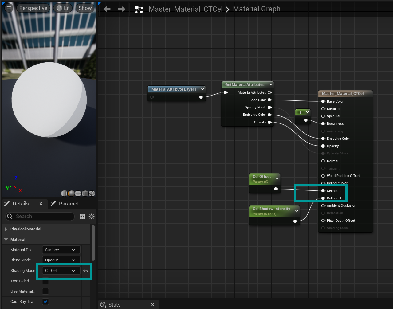
For this shading model, what I need is simple, I just use the two custom data pin for my Cel NoL offset and Cel shadow intensity.
Talking back to the shadow cast part, in DeferredLightingCommon.ush, add a new branch of attenuation calculation for the new shading model.
//===== CT CEL SHADING ======
float3 Attenuation = 1;
BRANCH
if (GBuffer.ShadingModelID == SHADINGMODELID_CTCEL)
{
    float offset = GBuffer.CustomData.x;

    BRANCH
    if (offset >= 1)
    {
        Attenuation = 1;
    }
    else
    {
        float NoL = saturate(dot(N, L) *0.5 + 0.5);
        half NoLOffset = saturate(NoL + offset);
        float LightAttenuationOffset = saturate( Shadow.SurfaceShadow + offset);

        Attenuation = step(0.2, NoLOffset) * LightAttenuationOffset;
    }
}
//===== CT CEL SHADING ======
So that I got a new attenuation value that can apply to the original soft shadow (after the Shadow.SurfaceShadow):
LightAccumulator_AddSplit( LightAccumulator, Lighting.Diffuse, Lighting.Specular, Lighting.Diffuse, LightColor * LightMask * Shadow.SurfaceShadow * Attenuation, bNeedsSeparateSubsurfaceLightAccumulation );The Sea :ocean:
Apparently the sea is taking an important role here and in a large portion.
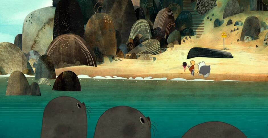
In the film, the sea mainly contains two parts: water foam and the textured base colour. The other details are splatters and some wavy lines near the foam.
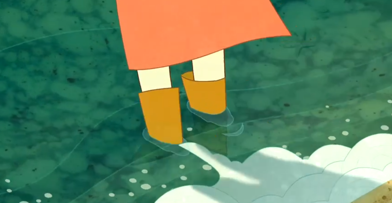
The sea shading in my project:arrow_down:

The sea layer
My sea shading contains two assets, one is the layer incharge of the basecolor and the flow moving, depth color variation, etc., named layer sea:
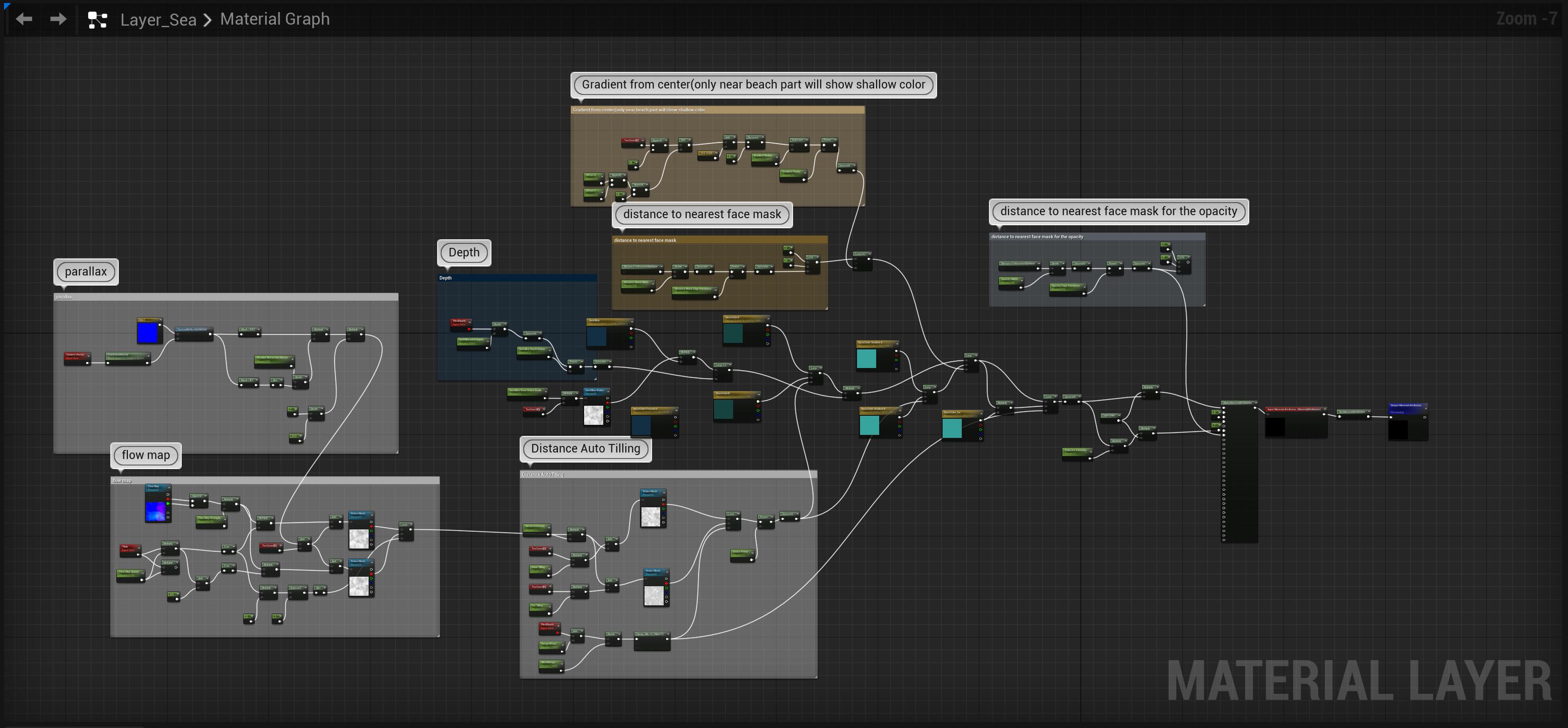
Flowmap
The first thing I considered is the flow direction of the water, as my landscape is a round shape, flow needs to move towards the center of the land. I use a flowmap to distort my water noise texture’s uv.
FlowMap Painter is so recommanded to draw your own flowmap:point_down:
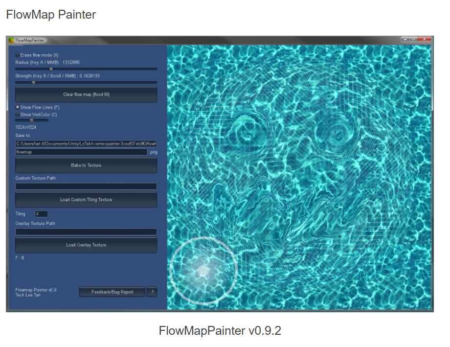
Parallax
I add some manipulation on the view direction’s Z channel to make some fake parallax effect, and plug it into the noise mask’s uv, to create a kind of water refraction effect.
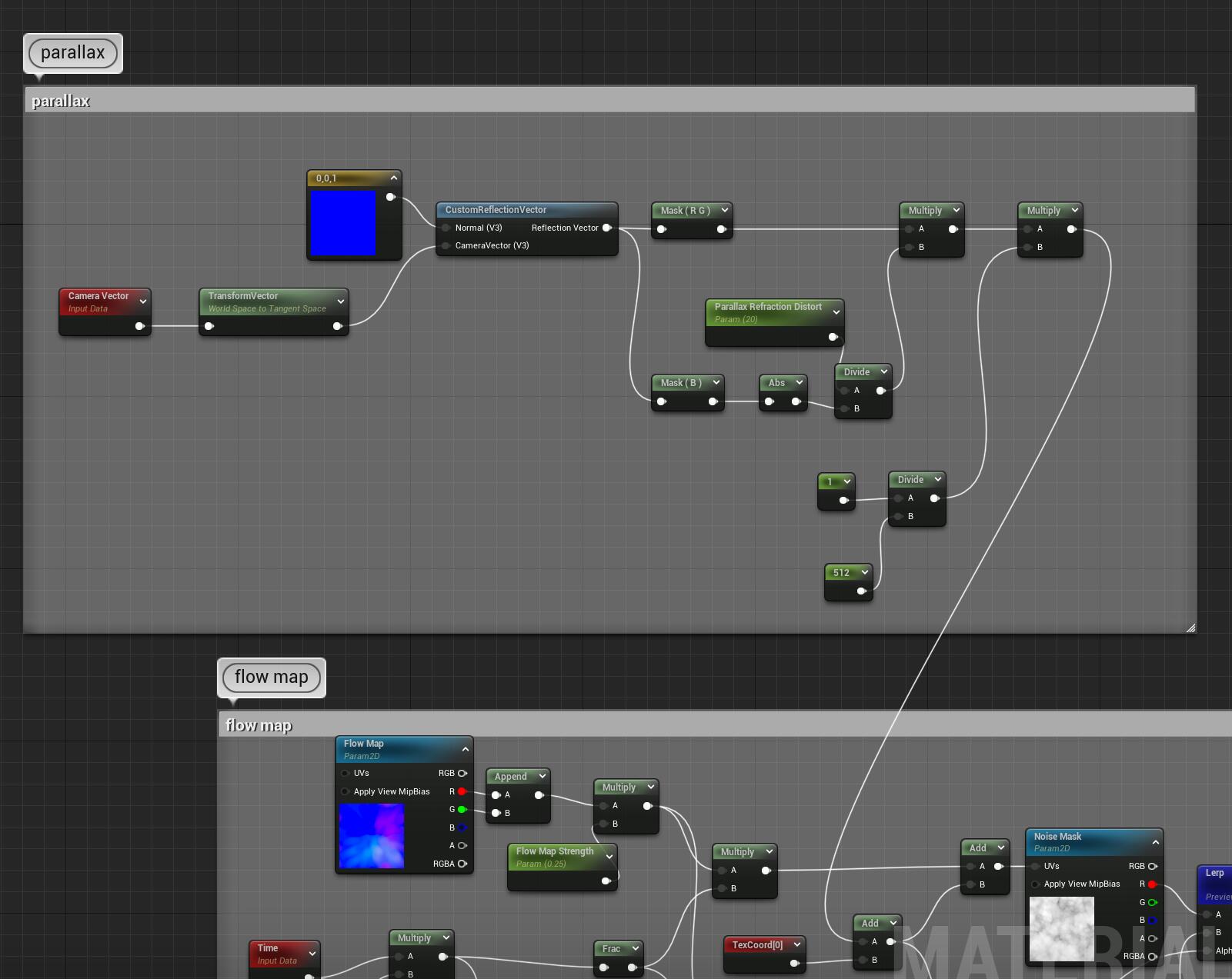
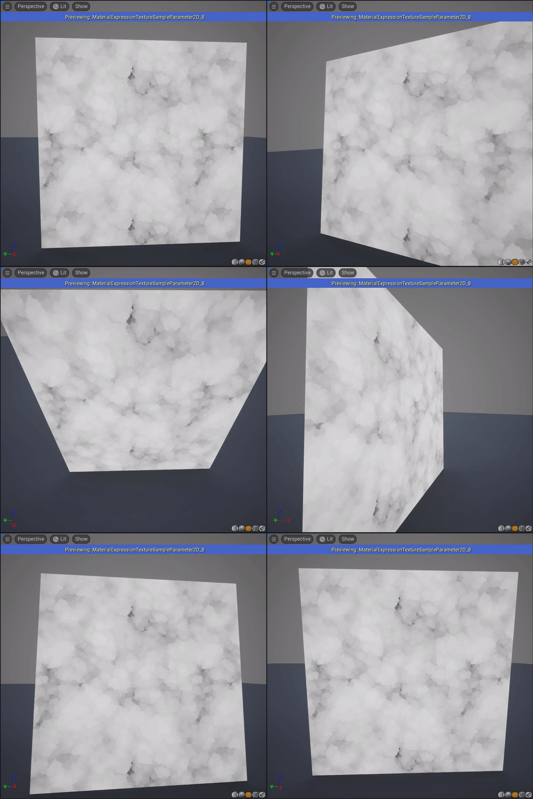
Distance to nearest face mask, DepthFade, PixelDepth
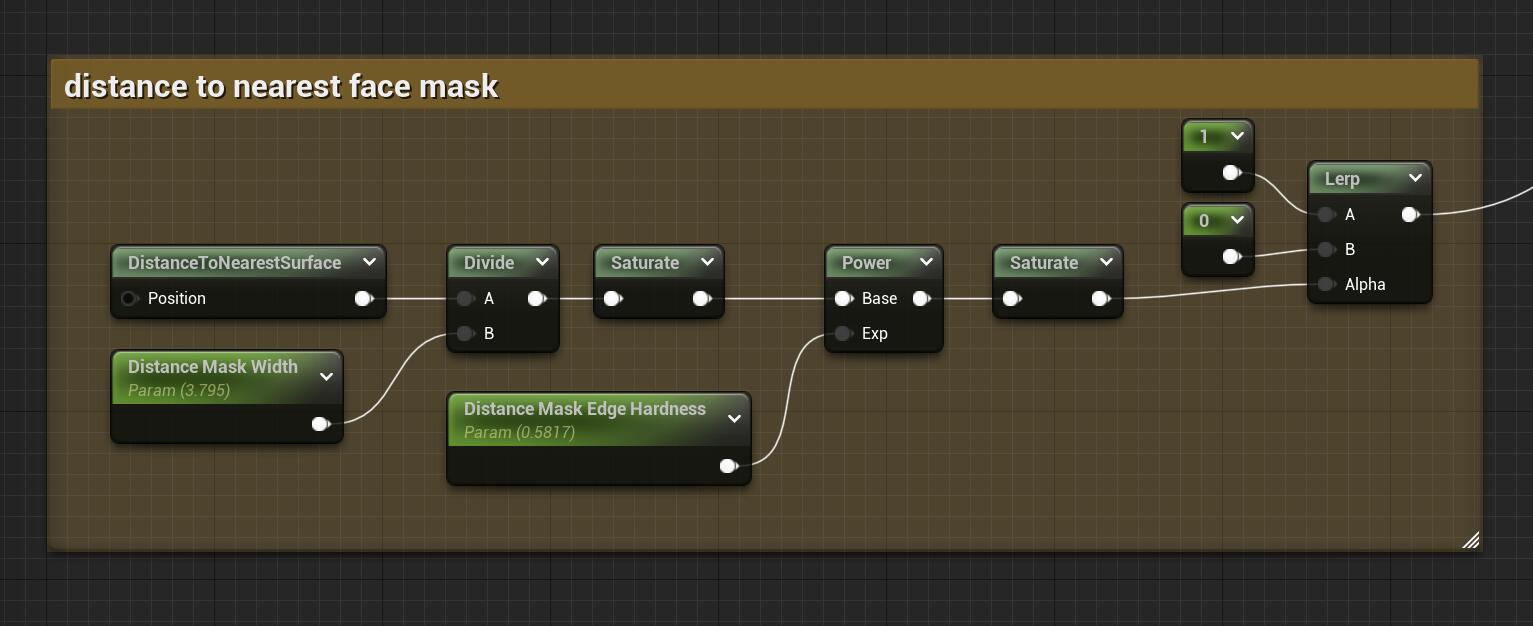
Distance to nearest mask give you a mask like below:point_down:
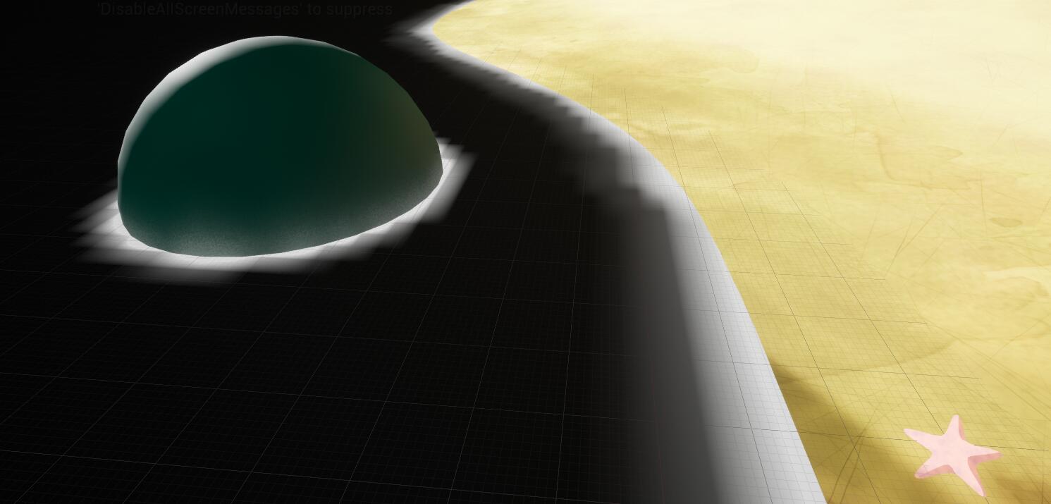
I applied the distance to nearest face mask as a lerp value to make color variation between blue to green, to differentiate the shallow and deep regions, and also the same mask method to plug into the opacity.
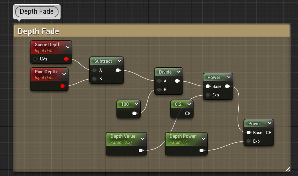
While the depth fade operation gives you the mask with depth effect, but I didn’t apply it in the sea material, just useful to mention how it works.
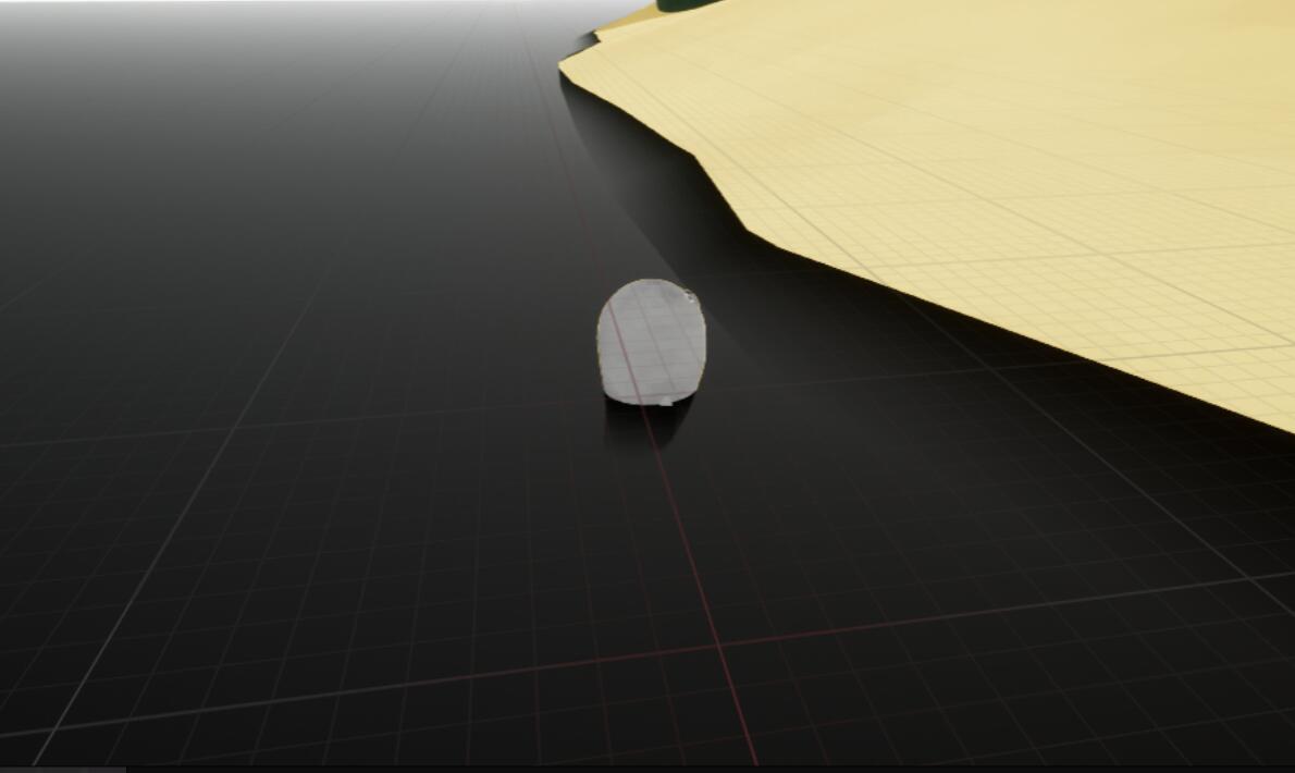
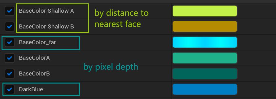
Another Color variation is based on the pixel depth. I need the water showing gradient when in a lower view position.
![]()
![]()
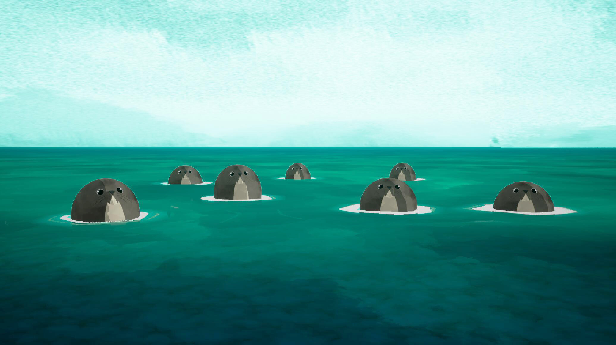
As a result I got the dark blue at the bottom part of this seals shot :point_down:
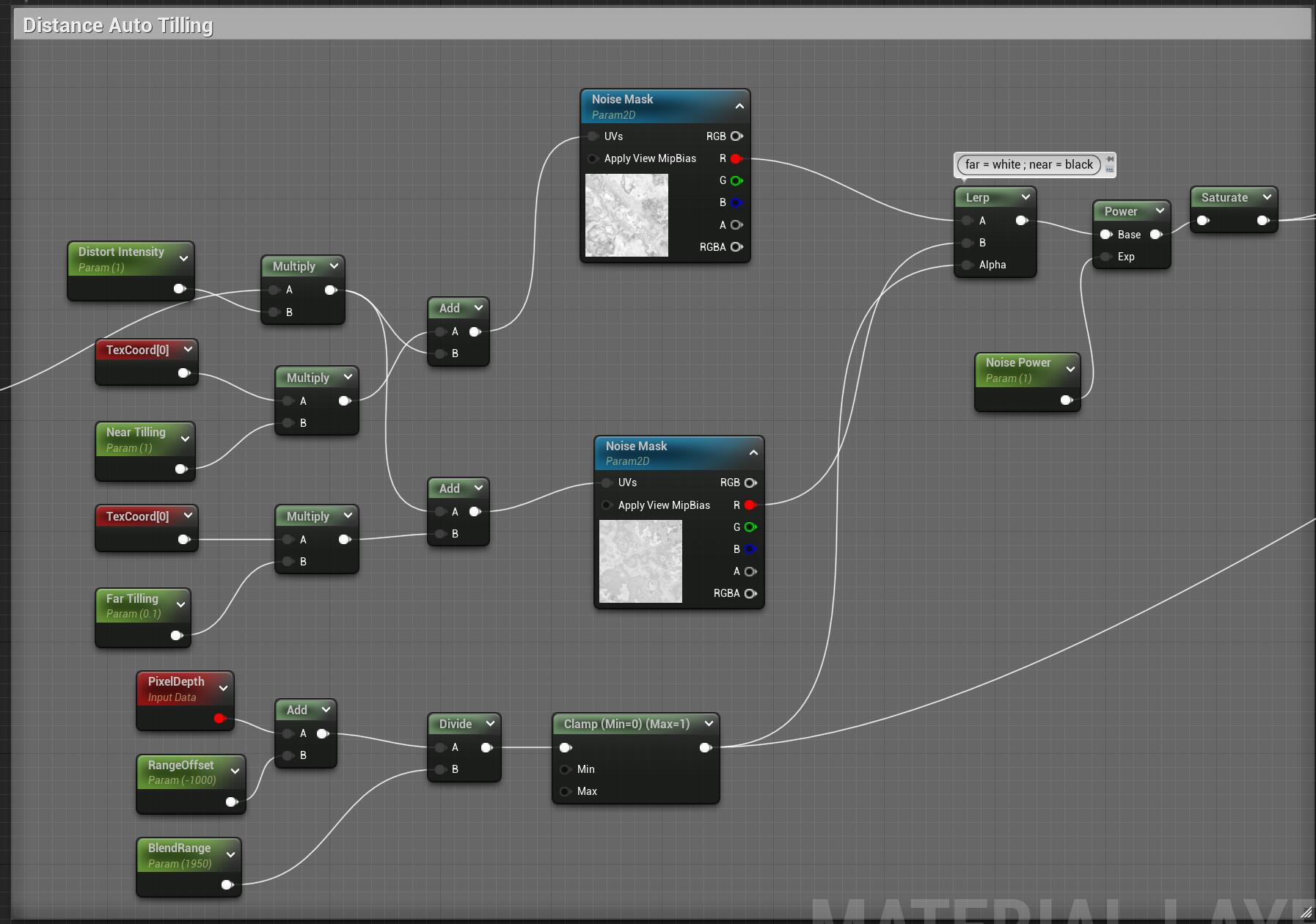
Distance tilling
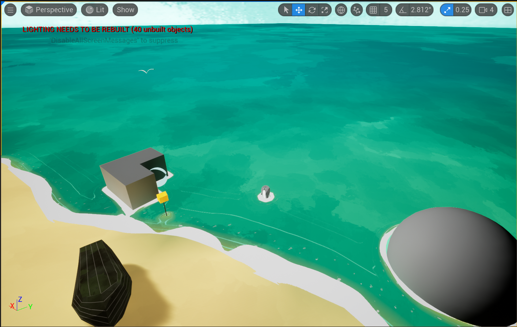
Distance tilling is lerping around by the depth to give different tilling at a different distance,so that when the near area is in a fit tilling, the pattern in the far area won’t be too crowded and repeated.
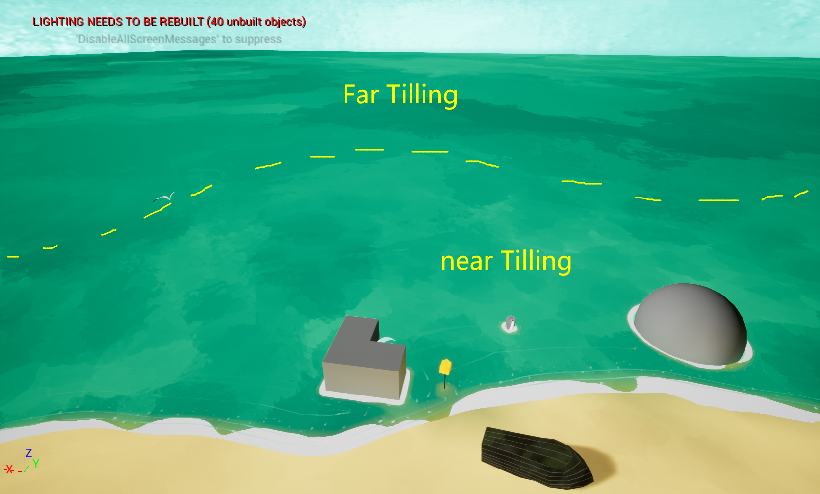
Below, applied with color variation in the near and far area.
The sea blend asset
Another asset I used to make the sea is a blend layer:
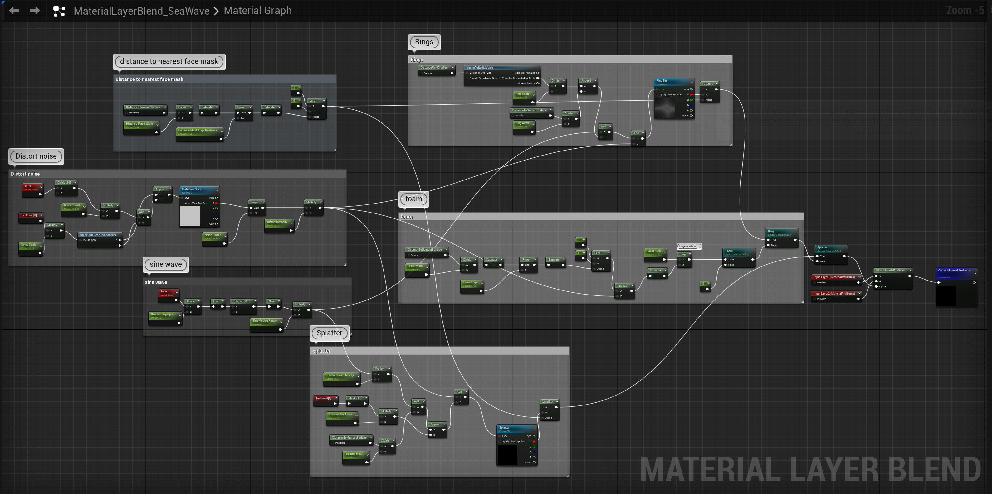
So this blend asset is used in the layering, I applied it to mask a solid color layer to mask out foam, rings and splatters. There are three toggles, for choosing a type of format.
The Foam
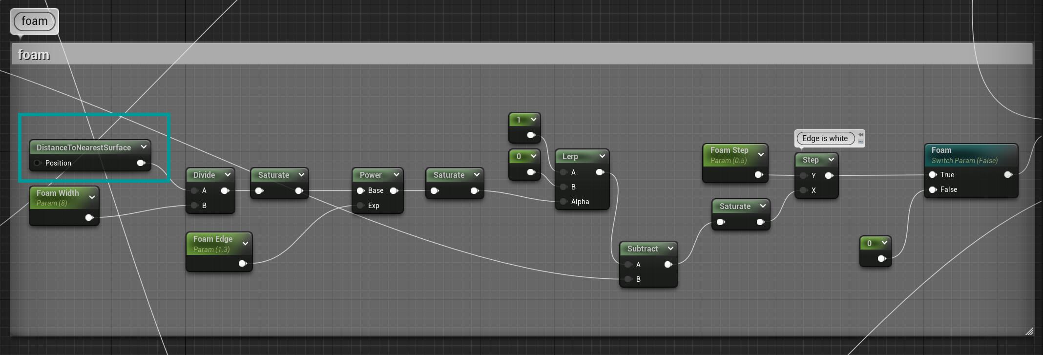
The foam function, was still, by using DistanceNearestToSurface node, increasing the power to make it with a harsh edge, and subtracting some distortion noises to make it moving and waving.
The Ring
For the ring effect, as I already had the ring range that can be created by DistanceNearestToSurface, but how to make it moving from each object’s center? It need to do something on uvs.

Looking at the below image, the contact area between each seals and the water surface, is actually a radial uv (created by the VectorToRadialValue), and that incoming XY value is not from a world position or mesh UV, but from DistanceFieldGradient, which can give you XYZ three channels of the distance nearest surface value. Then, I use this result as a single float, to append with DistanceToNearestSurface as the Y value, so that it restricted as the mask range, I can change it as the pattern’s width.

And the texture I used was just a simple strip tex:

Besides I plugged the distortion noise into the UV as well, to create the wavy effect.
The Splatter
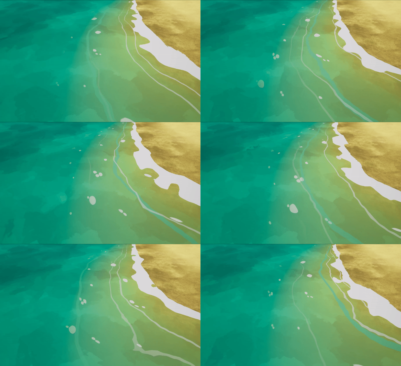
The splatter (what should be… random small foam I guess, not really water splatter) is simply texture with sine wave on uv and some distortion, nothing special.
Assemble together
Below are the layer parameters of my sea material instance. 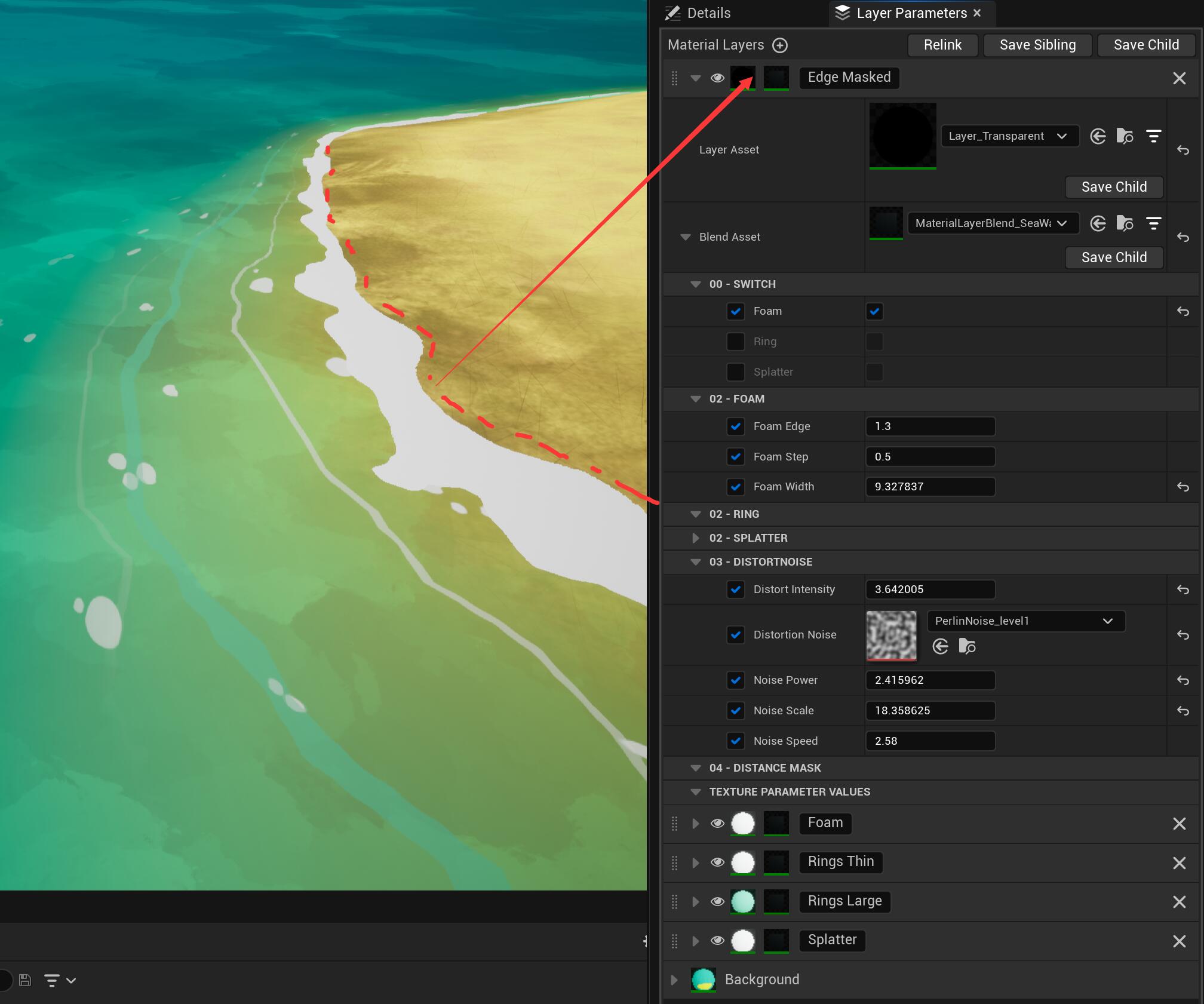
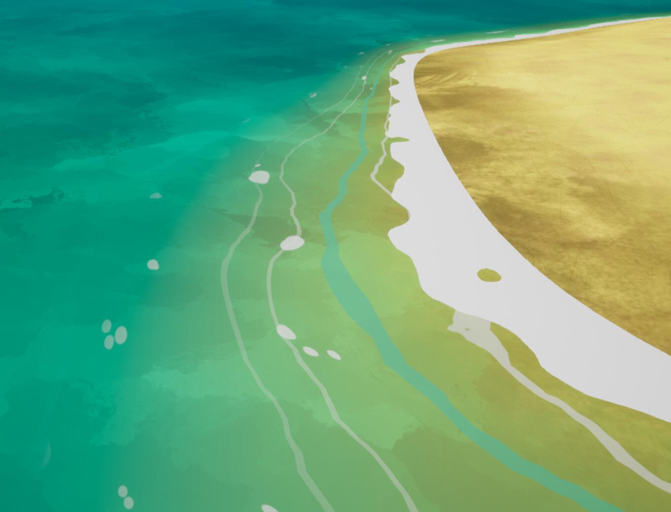
So the top layer is a transparent layer as a color layer, and placed same sea wave blend asset there so that the foam edge will appear the movement instead of a straight cutting line where the sea mesh plane intersects with the sand dune mesh.:point_down:
Saoirse
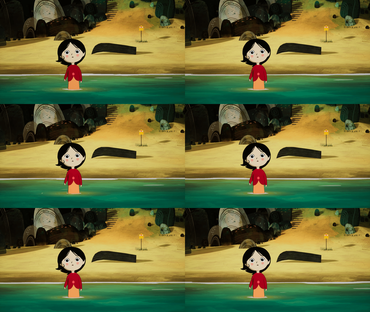
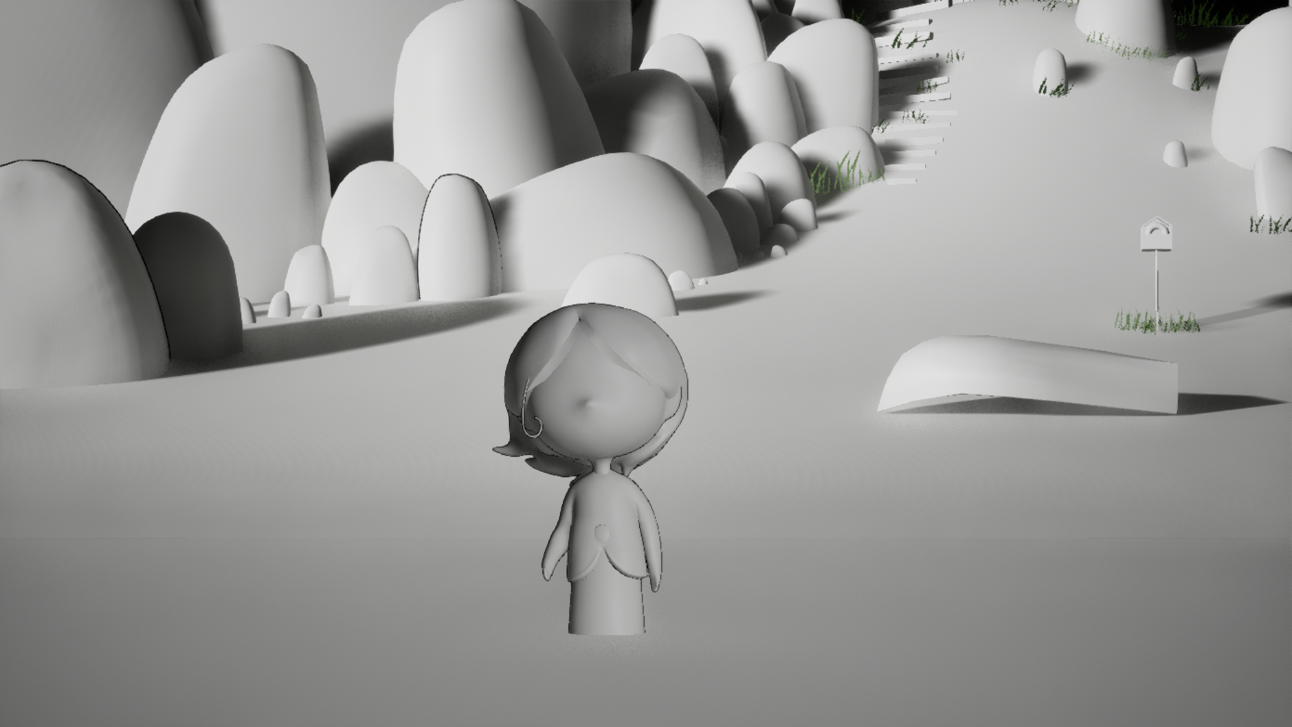
I don’t have a lot of experiences on modeling, fortunately everything in the film scene really doesn’t need a lot of complex 3d models, most of them are some basic shapes or some transformation based on that.
Shading
The colored part is same with other objects, by using layering materials. The Outline part is by using vertex offset along normal direction of a duplicated mesh. In Unity just need an additional pass cull front while in UE, I use TwoSidedSign and one minus it, plugged the result to the opacity mask, so that the front face will end up to be culled with the value 0. 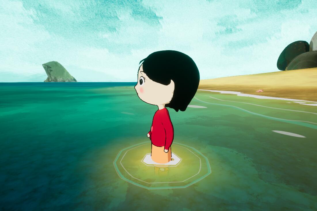
Rigging
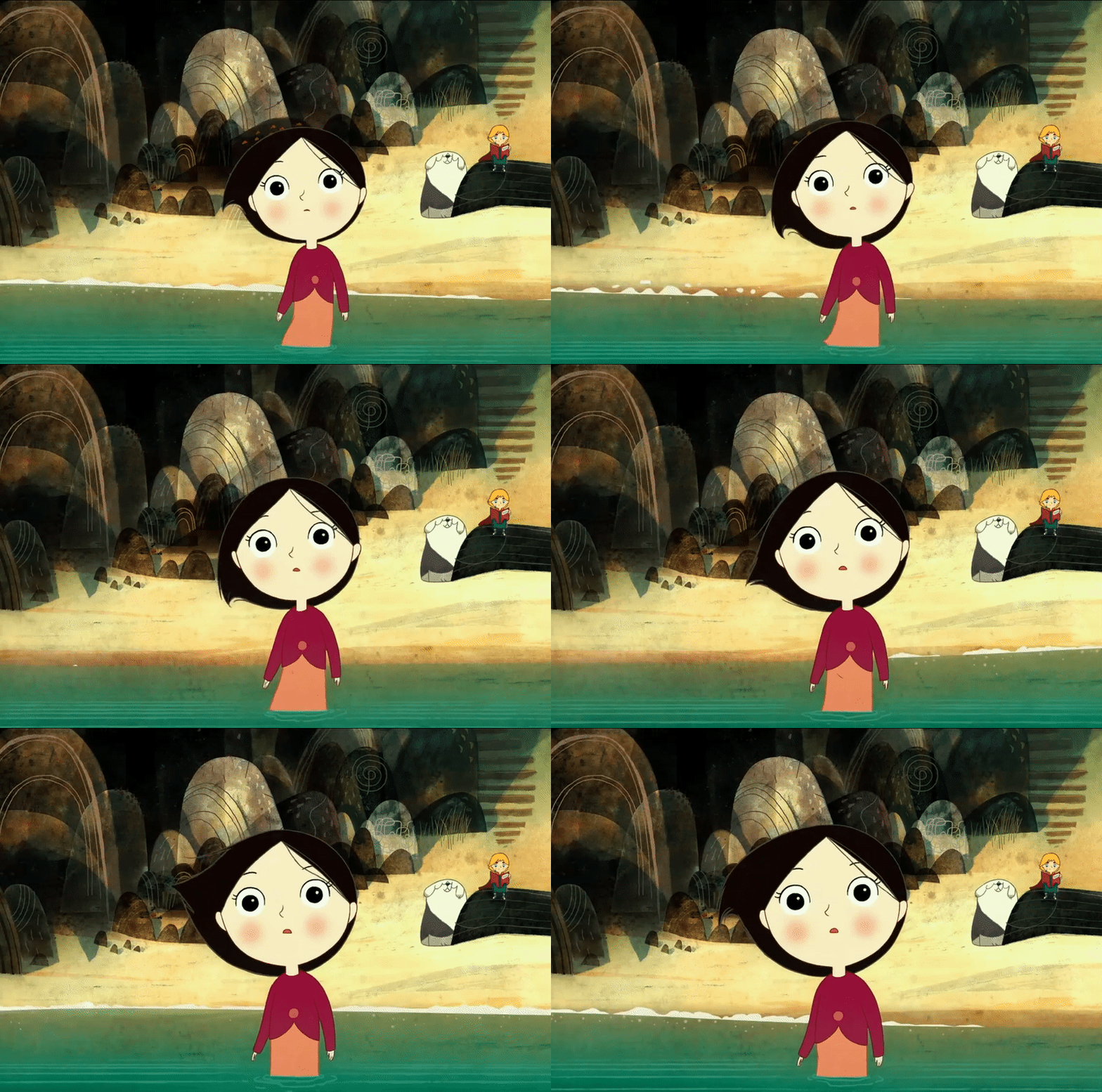
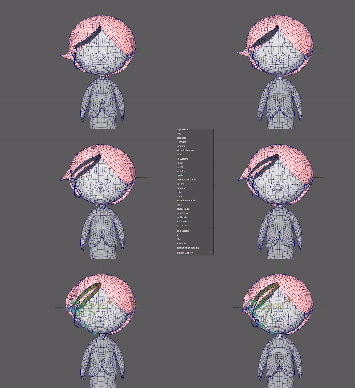
:arrow_up:In the film, her hair moving is very elastic feeling and moving like a ball rotating with swing up and down. Therefore I used bone rigging to mimic the swing effect around an appropriate centre pivot.
Foliage
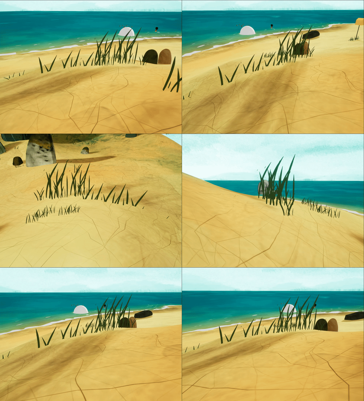
There are only grass and trees this scene of the film, both of them are really flat and with single solid color. Thus I make planes with alpha masked, and give function to make billboard effect, allowing the plane rotate always towards the viewer. 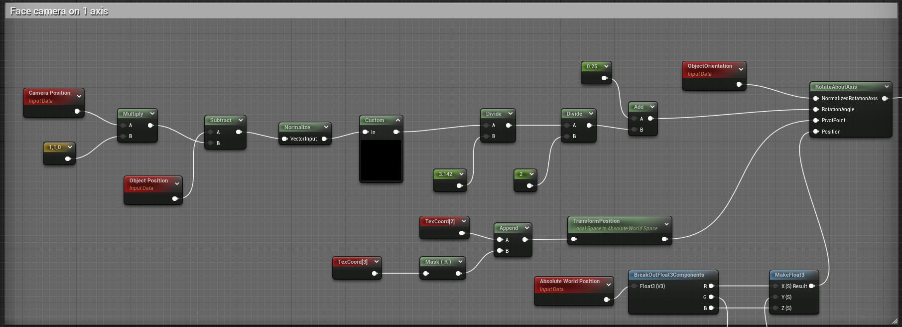
Vertex Animated Seagulls
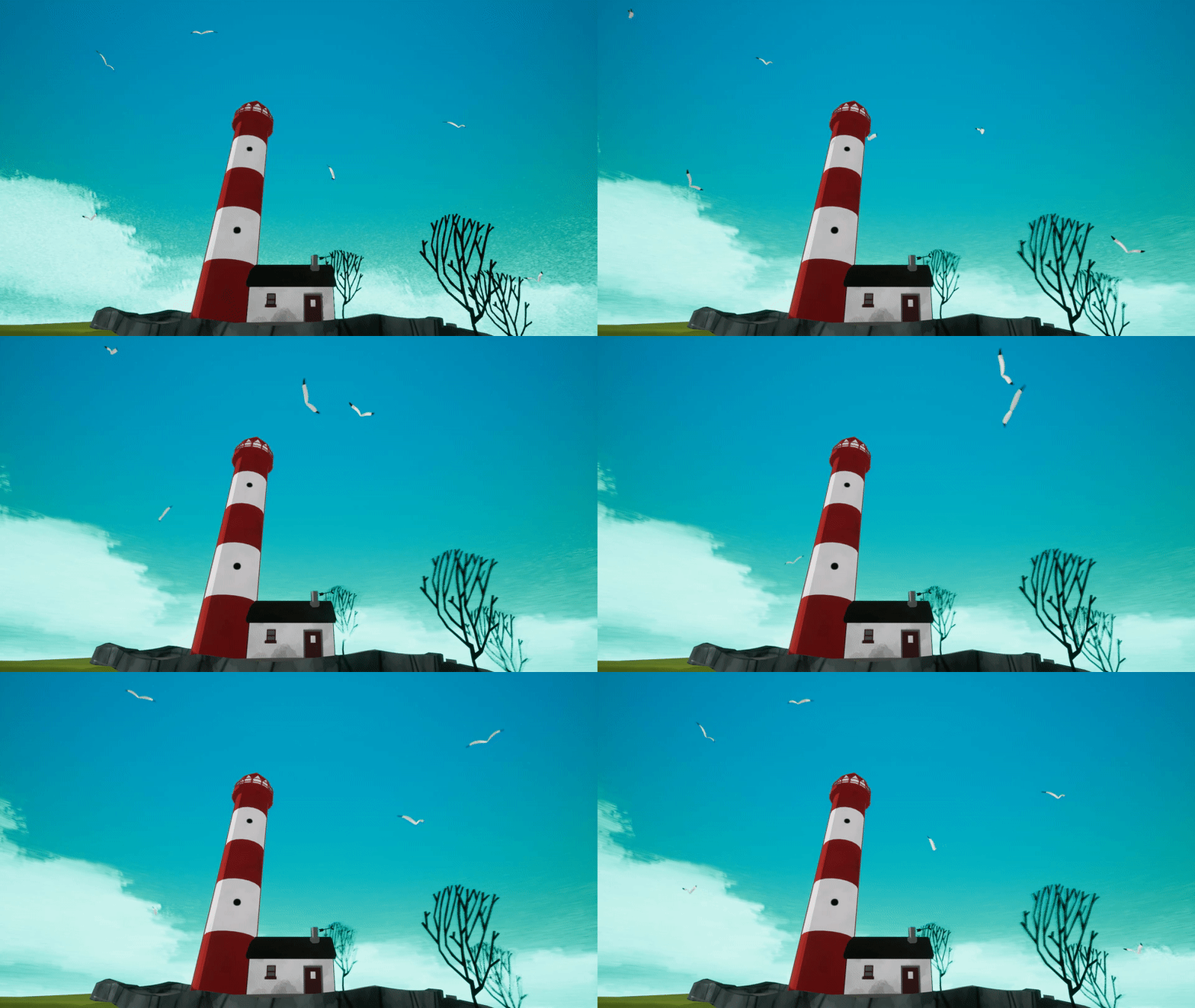
The seagull with a very simple mesh, and the wings’ UV align along the Y axis, so that I can using Y direction UV as a mask, to use a timing sine value as a lerp value to interpolate between the Y and 1-Y value. You’ll see clearly how it works in the gif below: 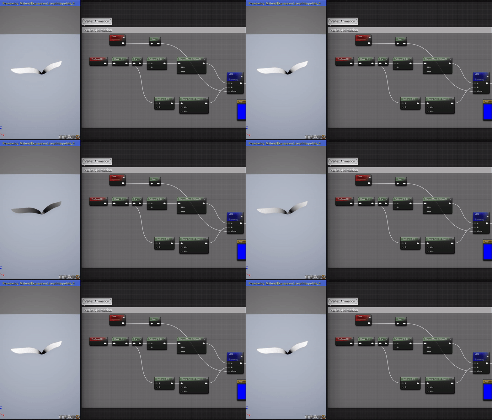
Then add this value to the Z channel of the vertex position, done!

