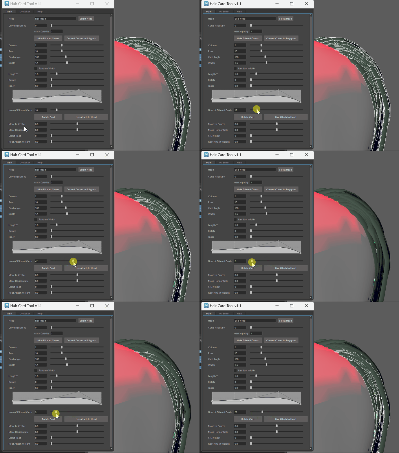
Maya Hair Card Tool
Intro
Recently, I encountered a requirement to develop a tool for converting HairStrands to HairCards. Unreal Engine already has a robust built-in feature for this, which works impressively well. However, we don’t use Unreal Engine, and developing a similar feature from scratch could take the development team up to a year. The prototype tool I’m tasked with creating focuses more on improving workflow efficiency, reducing manual adjustments, and streamlining the process. It’s not designed to be a magical, one-click solution for perfect hair cards but rather a helpful aid to optimize certain repetitive steps in the conversion workflow.
DCC Choice
Currently, artists are using Maya’s XGen to create HairStrands. While similar tools can be developed in Blender or Houdini, the workflow becomes cumbersome, requiring frequent switching and conversion between software. Therefore, I decided to develop this tool directly within Maya to ensure a smoother and more integrated workflow. Additionally, Maya’s Python API is robust and comprehensive, offering almost all the functionalities needed for geometric operations, making it an ideal choice for this task.
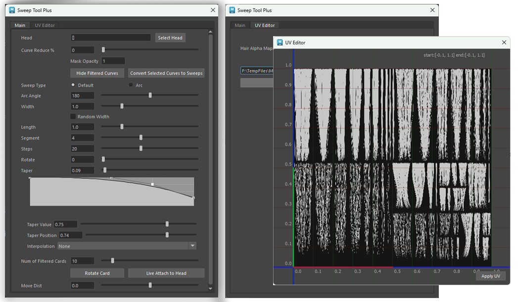
Maya has a built-in tool, previously part of the Bonus Tools and now located in a window named “Sweep,” which allows converting curves into polygons with adjustable properties like quad count, width, and rotation. However, it has a significant limitation: when working with multiple curves, you can either create a single Sweep node for all curves, causing them to share attributes, or generate individual Sweep nodes for each. The latter option doesn’t allow multi-selection or batch adjustments, making tweaking very inefficient.
So, part of my tool’s functionality is integrating Maya’s Sweep feature in a way that allows users to select multiple polygons and adjust them collectively through a single control panel, simplifying the process.
Convert Strands to Curves
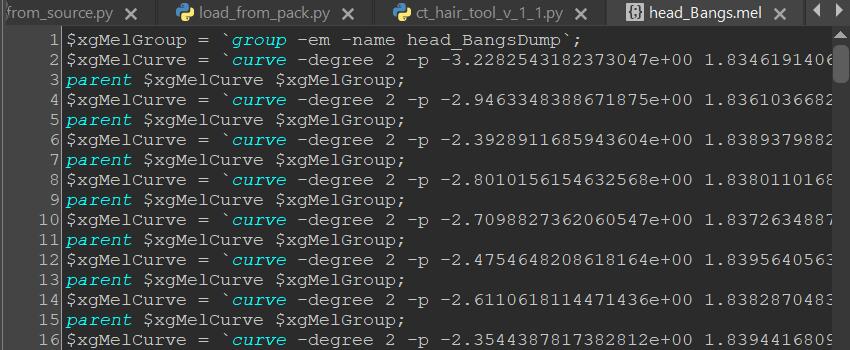
The first step is to retrieve the required curves. Maya XGen has a built-in feature that allows you to select a percentage of the desired strands. This process generates a lightweight MEL script containing all the point coordinate data of the curves. 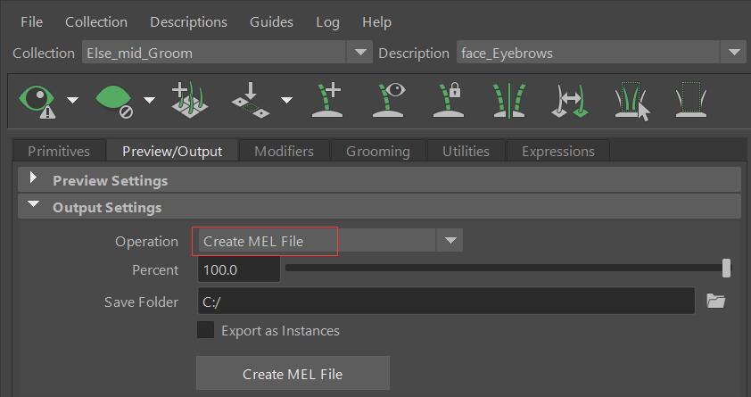 Running this script in Maya will recreate the curves directly in the scene.
Filter Curves
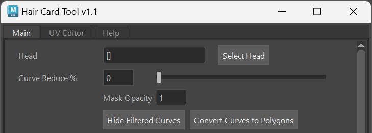
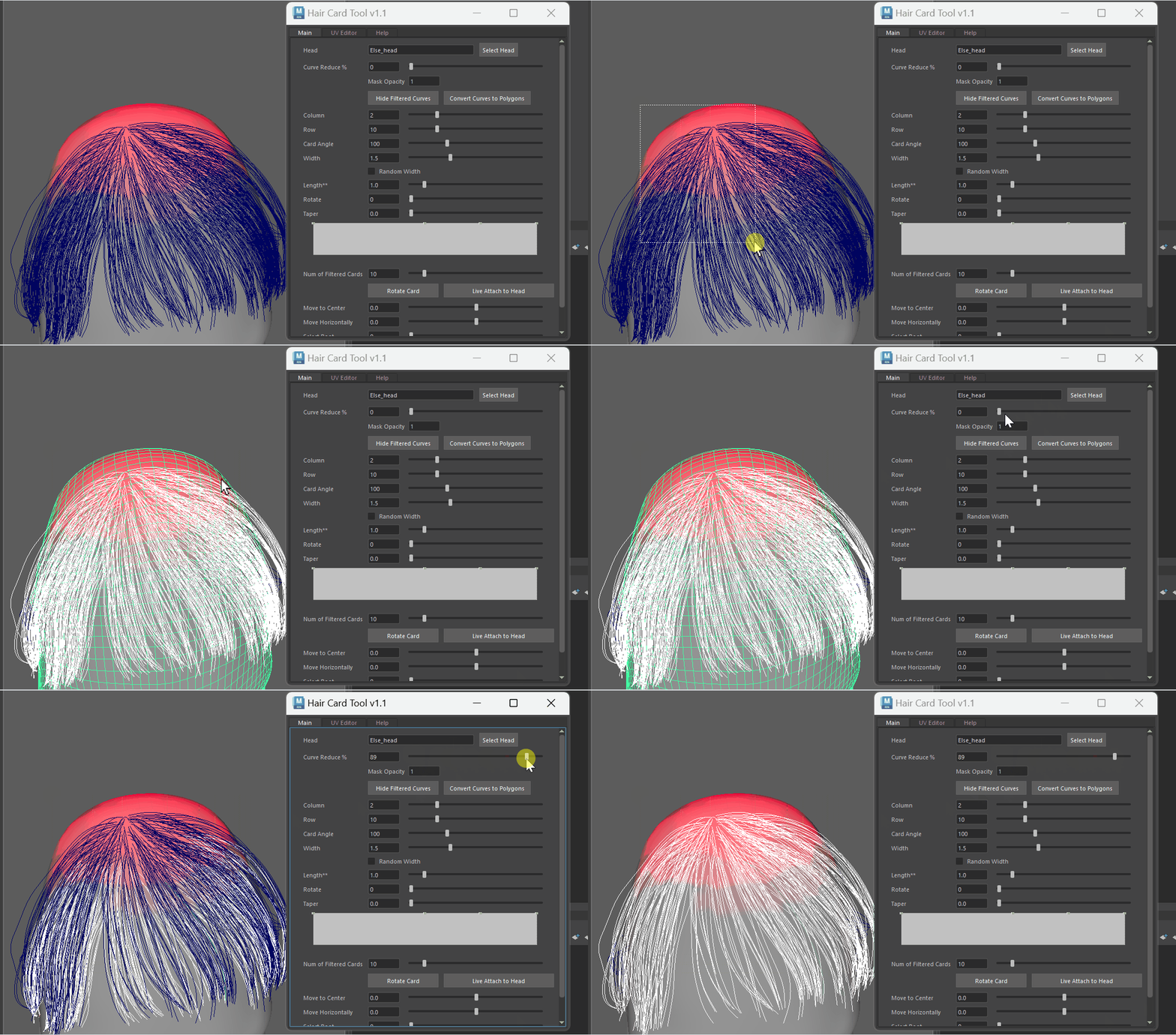
Once the curves are prepared, the first essential feature is curve filtering. I implemented a slider that allows users to select a percentage of unwanted curves—higher percentages result in more curves being selected. These selected curves can then be hidden using a Hide Filtered Curves button. To make the filtering more controllable—for example, the top of the head typically requires denser hair—you can paint red vertex colors in the desired areas. Curves falling within the vertex color regions won’t be selected or hidden, ensuring higher density, helping avoid exposing the scalp.
The Mask Opacity setting is used to adjust the transparency of the vertex color mask. If set to less than 1.0, curves within the vertex color coverage area may still be partially selected and hidden, allowing for finer control over which curves are kept visible and which are hidden, even in the designated areas.
Below is the function code for randomly selecting curves based on the percentage and checking if they are within the vertex color mask range:
1
2
3
4
5
6
7
8
9
10
11
12
13
14
15
16
17
18
19
20
21
22
23
24
25
26
27
28
29
30
31
32
33
34
35
36
37
38
39
40
41
42
43
44
45
46
47
48
49
50
51
52
53
54
55
56
57
58
59
60
61
62
    # Get those faces of head mesh that are painted
    def get_colored_face_dict(self):
        head_dp = om.MSelectionList().add(self.sel_head).getDagPath(0)

        colored_face_dict = {}
        head_face_len = cmd.polyEvaluate(self.sel_head, face = True)
        mesh = om.MFnMesh(head_dp)
        sourceColors = om.MColor()
        vert_colors = mesh.getVertexColors('colorSet1', sourceColors)
        m_vert_iter = om.MItMeshVertex(head_dp)
        for vert in m_vert_iter:
            if vert_colors[vert.index()][0]> 0.0:
                find_faces = vert.getConnectedFaces()
                for f in find_faces:
                    if f not in colored_face_dict.keys():
                        colored_face_dict.update({f : vert_colors[vert.index()][0]})
        return colored_face_dict

    # Select curves randomly based on a percentage
    def random_curve_selection(self, input):

        try:
            head_dp = om.MSelectionList().add(self.sel_head).getDagPath(0)
        except:
            cmd.warning( "No Head Selected" )
            return

        # sel_curves = cmd.ls(long=True, selection=True)
        if not self.lock_curves:
            cmd.warning( "No Curves Selected" )
            return

        cmd.select(self.lock_curves)
        curve_visible_list = cmd.filterExpand(sm = 9) # filter only curves
        colored_face_dict = self.get_colored_face_dict()
        set_reduce_percent = input/100 #40
        reduce_percent = set_reduce_percent #40%
        vc_mask_opacity = self.update_vc_mask(self.le_vc_mask.text())
        keep_num = len(self.lock_curves) * (1-reduce_percent) # 100*0.4 keep 60
        cmd.select(clear = True)
        while(len(curve_visible_list)) > keep_num: # when keep curves > 60, continue
            for curv in curve_visible_list:
                first_cv = f'{curv}.cv[0]'
                first_cv_pos = cmd.pointPosition(first_cv)
                closest_vert_pos, closest_face_id = om.MFnMesh(head_dp).getClosestPoint(om.MPoint(*first_cv_pos))

                if closest_face_id in colored_face_dict.keys():
                    reduce_factor = self.clamp(colored_face_dict[closest_face_id], 0.0, 1.0) * vc_mask_opacity
                    reduce_percent *= (1 - reduce_factor)

                if (reduce_percent < 0.1):
                    if curv in curve_visible_list:
                        curve_visible_list.remove(curv)

                if(random.random() < reduce_percent): # if whithin 0.4, delete
                    cmd.select(f'{curv}', af=True)
                    if curv in curve_visible_list:
                        #cmd.hide(curv)
                        curve_visible_list.remove(curv)
                        cmd.select(f'{curv}', add=True)
                reduce_percent = set_reduce_percent
Float Qt Slider
Qt’s Slider widget only supports integer values, meaning the slider’s minimum step size is limited to 1. To allow for decimal values, you would need to adjust the slider’s behavior by manually scaling the values.
So most of my UI consists of a QLabel, a QLineEdit, and a QSlider. For example, with a width property, I want the slider’s range to be (0, 5.0). The actual range of my QSlider would be (0, 500). When the slider value changes, it triggers function update_line_edit_float that updates the value displayed in the QLineEdit as QSlider.value()/100. Similarly, when the QLineEdit value changes, it triggers update_line_edit_float to synchronize both UI elements.
1
2
3
4
5
    def update_slider_float(self, slider_widget, input):
        slider_widget.setSliderPosition(float(input) * 100)

    def update_line_edit_float(self, line_edit_widget, input):
        line_edit_widget.setText(str(input/ 100))
Column, Row, Angle, Width, Rotate
For parameters like Column, Row, Angle, Width, and Rotate, I can directly link them to the corresponding parameters in the selected polygons’ Sweep nodes, I can use cmds.SetAttr() to batch modify them. This operation is straightforward, so I won’t go into further detail here.
Taper Curves
 For the taper functionality, I used Maya’s cmds API function
 falloffCurveAttr. This function requires first creating an attribute group node, then add necessary attributes to the ramp node using addAttr; and the keys on that curve can be referenced as xxx.xxxcurve[i]to add keys on the curve. The taper feature code is below:
1
2
3
4
5
6
7
8
9
10
11
12
13
14
15
16
    # Taper Curve
    if cmd.ls('ramp_node'):
        cmd.delete('ramp_node')
    cmd.group(em=True, n = 'ramp_node')
    cmd.addAttr('ramp_node', attributeType='compound', ln='taper_curve',numberOfChildren = 3, multi=True)
    cmd.addAttr('ramp_node', at='float', ln='taper_curve_pos', p='taper_curve', defaultValue= 1) #position
    cmd.addAttr('ramp_node', at='float', ln='taper_curve_val', p='taper_curve', defaultValue= 1) #value
    cmd.addAttr('ramp_node', at='enum', ln='taper_curve_type', p='taper_curve', enumName = 'None:Linear:Smooth:Spline', defaultValue= 1, min = 0, max = 3) #interp
    cmd.setAttr('ramp_node.taper_curve[0]', 0, 1, 2) #position, value, interp
    cmd.setAttr('ramp_node.taper_curve[1]', 0.5, 1, 2) #position, value, interp
    cmd.setAttr('ramp_node.taper_curve[2]', 0.75, 1, 2) #position, value, interp
    cmd.setAttr('ramp_node.taper_curve[3]', 1, 1, 2) #position, value, interp

    self.curve_attr = cmd.falloffCurveAttr( 'Taper Curve', h=90, attribute = 'ramp_node.taper_curve', changeCommand = functools.partial(self.update_current_curve_sliders))
    curve_attr_qwidget = omui.MQtUtil.findControl(self.curve_attr) # Wrap Maya cmd UI to Qt Widget
    curve_attr_qwidget = wrapInstance(int(curve_attr_qwidget), QtWidgets.QWidget)
Length
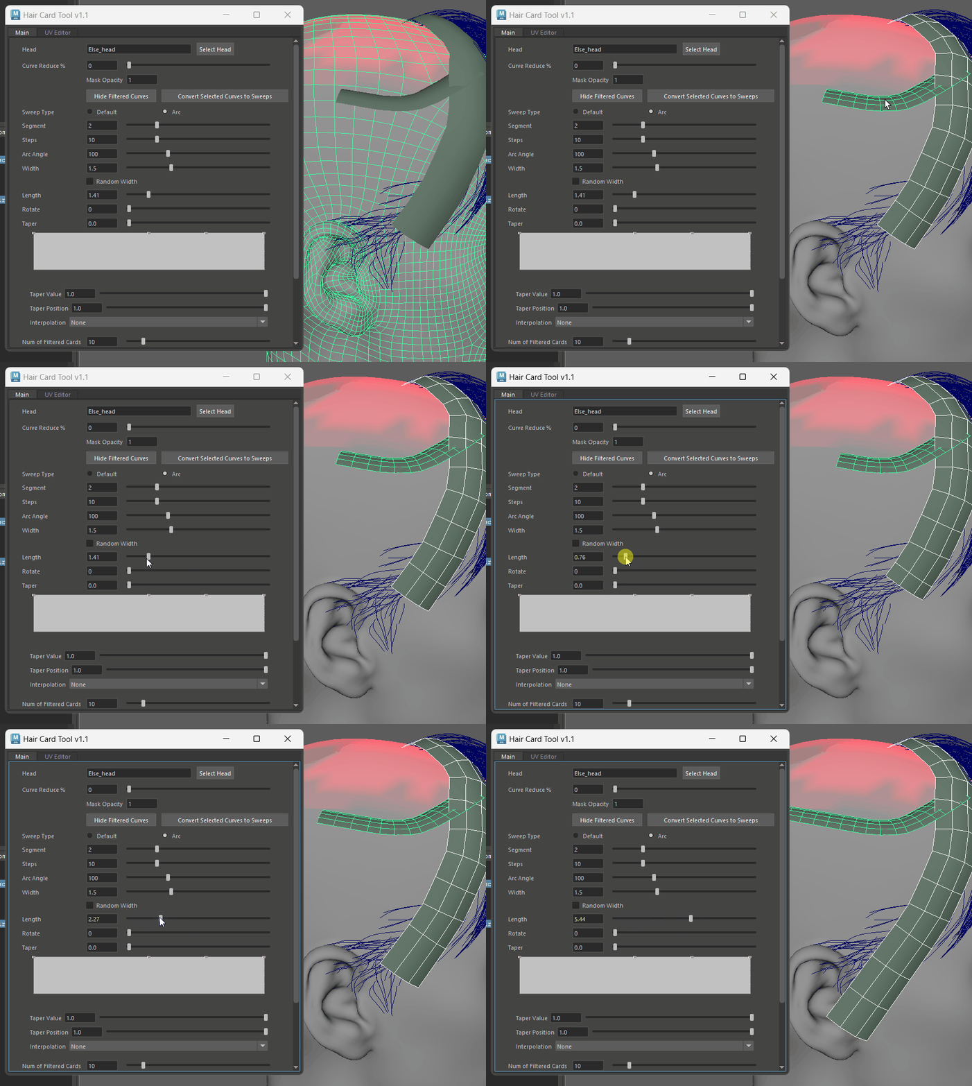 The SweepTool lacks a built-in function to control length. Initially, I tried simply stretching the polygons along the Y-axis, but this caused deformation and didn’t work well for horizontally placed polygons. Later, I used the Extrude function to extend polygons by adding new faces at the ends, and automatically adjusts the division count based on the extended length.
First, the indices of the edges at the very end must be identified. From the sweep attributes, I can obtain the number of polygon columns (e.g., 3). Thus, the last 3 faces correspond to the last row of the card. Among these faces, I locate the third edge, which represents the bottom edge of each quad. These three edges are then stored in a dictionary, preparing them for the next extrusion step.
1
2
3
4
5
6
7
8
9
10
11
12
13
14
15
16
17
18
19
20
21
22
23
24
25
    def find_card_edge(self, undo_name):
        self.undo_on(undo_name)
        # input = input/100
        self.sel_cards = cmd.ls(sl = True, type = 'transform')
        self.extrude_card_edge_dict = {}

        for card in self.sel_cards:
            if 'sweep' in str(card):
                card_dp = om.MSelectionList().add(card).getDagPath(0)
                poly_iter = om.MItMeshPolygon(card_dp)
                # creator = self.find_sweep_creators() #[['sweepMeshCreator2'], ['sweepMeshCreator3']]
                shape = cmd.listRelatives(card)
                creator = cmd.findType(shape, deep=True, type='sweepMeshCreator')[0]
                segment = cmd.getAttr(f'{creator}.profileArcSegments') # Num of the column of the card
                face_index_list = []
                edge_index_list = []
                for f in poly_iter:
                    face_index_list.append(f.index())
                    edge_index_list.append(f.getEdges())
                last_few_edges = edge_index_list[-segment:]
                extrude_edges = []
                for e in last_few_edges:
                    edge_name = f'{card}.e[{e[2]}]' #the third edge of every face
                    extrude_edges.append(edge_name)
                self.extrude_card_edge_dict.update({card:extrude_edges})
In the exec_extrude_edge function, I use MItMeshEdge to find the length of edge #1 (one of the side edges of the first face), which represents the height of each row. When a length value is entered via the slider, it is divided by the row’s height, and the integer result determines the number of divisions. This ensures that divisions are automatically added based on the extended length:
1
2
3
4
5
6
7
8
9
10
11
12
13
14
15
16
17
18
19
20
21
22
23
24
25
26
27
28
29
30
31
32
33
34
35
36
37
    def exec_extrude_edge(self, slider, undo_name):

        input = slider.value()/100
        # Extrude
        for k in self.extrude_card_edge_dict.keys():
            print(f'k = {k}')
            # get edge length:
            card_dp = om.MSelectionList().add(k).getDagPath(0)
            edge_iter = om.MItMeshEdge(card_dp)

            edge_length = 1.0  # init
            for e in edge_iter:
                if e.index() == 1:
                    edge_length = e.length()
                    print(f'edge_length = {edge_length}')
                    break

            shape = cmd.listRelatives(k)[0]
            print(f'shape = {shape}')
            extrude_node = cmd.findType(shape, deep=True, type = 'polyExtrudeEdge')
            print(f'extrude_node = {extrude_node}')
            if extrude_node == None:
                extrude_node = cmd.polyExtrudeEdge(self.extrude_card_edge_dict[k], lty = 1.0, divisions = 0)
                print(f'extrude_node2 = {extrude_node}')

            cmd.setAttr(f'{extrude_node[0]}.localTranslateY', input)
            cmd.setAttr(f'{extrude_node[0]}.smoothingAngle', 60)
            print(f'{extrude_node[0]}.localTranslateY')

            # Find Division
            div = math.floor(input / edge_length)
            if div < 1:
                div = 1
            cmd.setAttr(f'{extrude_node[0]}.divisions', div)
            print(f'div = {div}')

        self.undo_off(undo_name)
Filter Cards by Distance to the scalp
This feature is designed to filter out polygons closer to the scalp. I calculate the distance between the center of each card and the center of the head mesh, then sort them into a list based on this distance.
1
2
3
4
5
6
7
8
9
10
11
12
13
14
15
16
17
18
19
20
21
    def make_card_list_by_distance(self):
        #self.sel_cards = cmd.ls(sl = True)
        self.dist_dict = {}
        for card in self.lock_cards:
            card_center = cmd.objectCenter(card)
            dist = math.dist(card_center, self.head_center)
            self.dist_dict.update({card: dist})

        self.dist_dict = dict(sorted(self.dist_dict.items(), key=lambda item: item[1]))
        #return self.dist_dict

    def slider_inner_cards_select(self, input):
        self.make_card_list_by_distance()
        self.cards_num = len(self.lock_cards)

        cmd.select(clear = 1)
        input = int(input)
        if input > self.cards_num:
            input = self.cards_num
        for i in range(input):
            cmd.select(f'{list(self.dist_dict.keys())[i]}', af= True)
Move Towards the Scalp
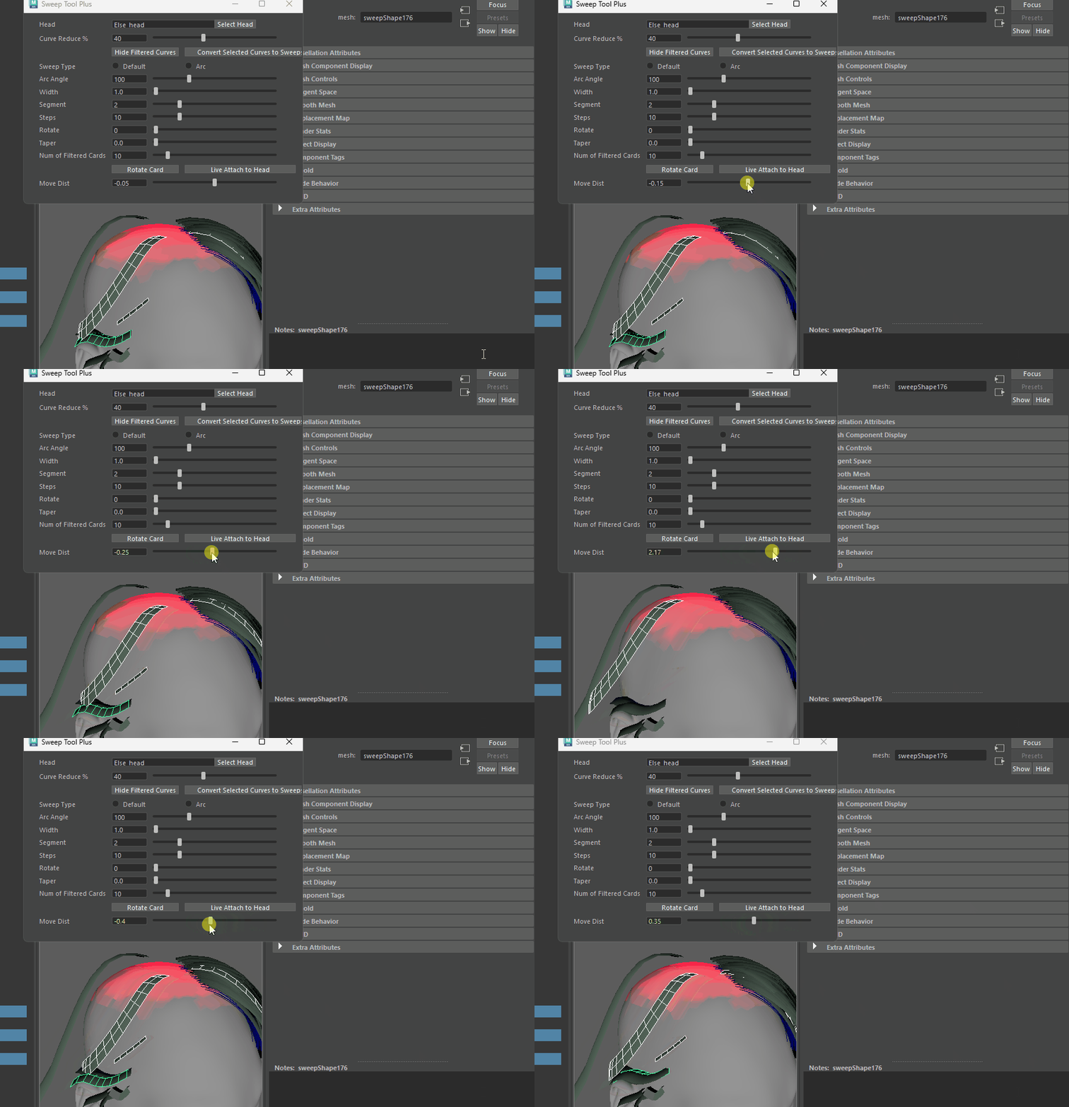
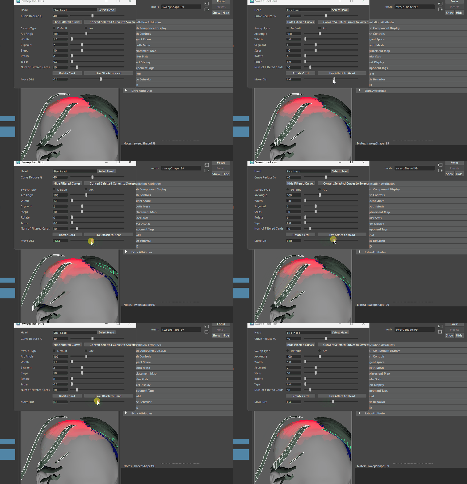
This feature adjusts the distance between hair cards and the scalp. I find the center point of each card, then by using the om.MFnMesh.getClosestPoint function to find the closest point of head scalp to that center point. The cards then move along this vector.
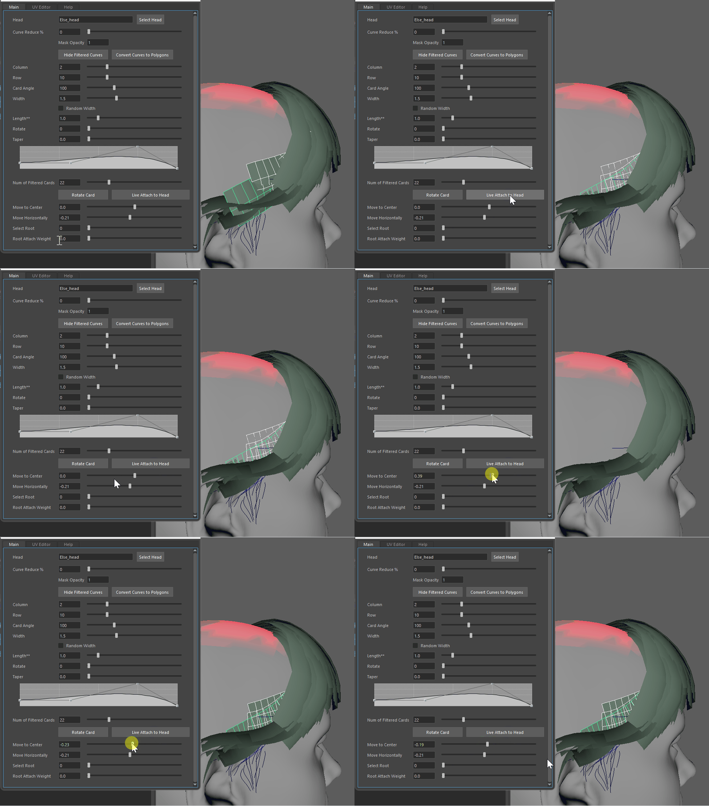
Initially, I calculated the direction vector using head point - card center, but this approach caused inconsistent movement directions for cards positioned on the left and right sides of the head:
Ideally, regardless of their location, the cards should always move directly toward the scalp. So, I added a directional check in the function. If the product of the card_to_head vector and the direction vector is negative, it indicates the moving direction is reversed. In this case, the direction vector is multiplied by -1 to correct it, see the Line 26-28 in the following code:
1
2
3
4
5
6
7
8
9
10
11
12
13
14
15
16
17
18
19
20
21
22
23
24
25
26
27
28
29
30
31
32
33
34
35
36
37
38
39
40
41
42
43
44
45
    def slider_lock_move_direction(self):
        self.new_point_dict = {}

        try:
            head_dp = om.MSelectionList().add(self.sel_head).getDagPath(0)
        except:
            cmd.warning( "No Head Selected" )
            return

        inner_cards = cmd.ls(sl = True, type = 'transform')
        if not inner_cards:
            cmd.warning( "There's no Card Selected" )
            return

        head_mesh = om.MFnMesh(head_dp)
        head_center = cmd.objectCenter(self.sel_head)

        for card in inner_cards:
            curve = cmd.filterExpand(card, sm = 9)
            if not curve:
                #print(f'card:{card}')
                card_center = cmd.objectCenter(card)
                card_to_head = om.MVector(head_center) - om.MVector(card_center)
                closest_head_vert = head_mesh.getClosestPoint(om.MPoint(*card_center))
                direction = om.MVector(closest_head_vert[0]) - om.MVector(card_center)
                for i in range(3):
                    if card_to_head[i] * direction[i] < 0: # Correct the moving direction
                        direction[i] *= -1


                direction = om.MVector(*direction).normalize()
                card_position = cmd.xform(card, query = True, scalePivot = True)
                card_position = om.MVector(*card_position)

                self.new_point_dict.update({card: [card_position, direction]})

    # Move function
    def slider_move_cards_to_closest_face(self, input):
        self.undo_on('move dist')
        if not self.new_point_dict:
            return

        for item in self.new_point_dict.items():
            new_point =  item[1][0] + item[1][1] *(input/100)
            cmd.xform(item[0], translation = new_point)
Rotate Cards
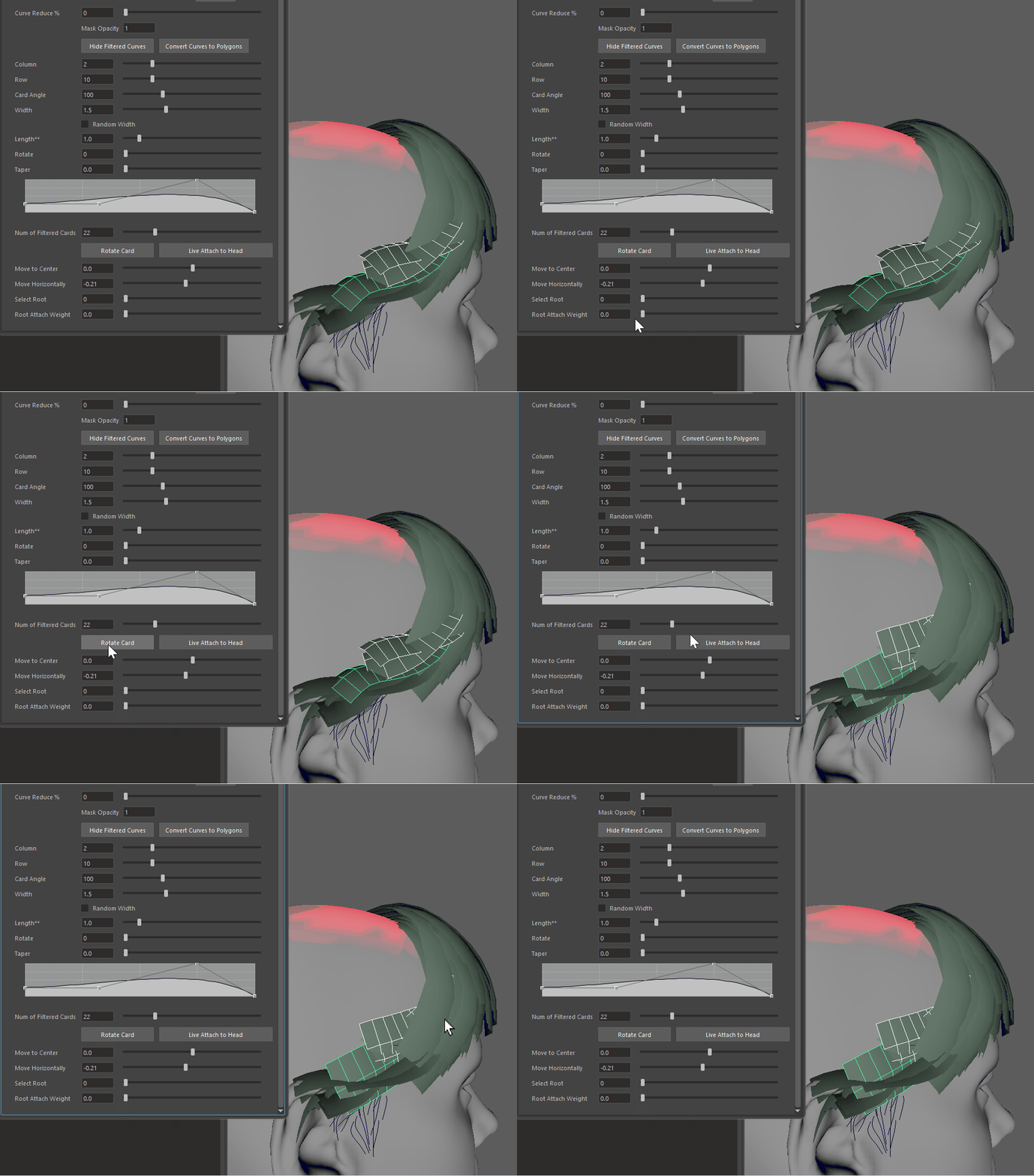
Although the Sweep Tool includes a polygon rotation feature, I created a one-click rotation functionality. This tool calculates the center point and normal vector of each card’s face, finds the closest point on the scalp to the center point, and determines its normal vector. Using these pairs of normals, it calculates Euler values for rotation, averages them, and applies the average Euler rotation to the card using its center point as the pivot.
Get Euler between two vectors:
1
2
3
4
5
6
7
8
9
10
11
12
13
14
15
    def get_euler(self, head_closest_normal, card_poly_normal, head_xform, card_xform, card_poly, card_poly_center):
        head_closest_normal = om.MVector(*head_closest_normal)
        card_poly_normal = om.MVector(*card_poly_normal)
        head_xform_mtx = cmd.xform(head_xform, query = True, worldSpace= True, matrix = True)
        card_xform_mtx = cmd.xform(card_xform, query = True, worldSpace= True, matrix = True)
        head_matrix = om.MMatrix(head_xform_mtx)
        card_matrix = om.MMatrix(card_xform_mtx)
        head_closest_normal *= head_matrix
        card_poly_normal *= card_matrix

        rotation = card_poly_normal.rotateTo(head_closest_normal)
        euler = rotation.asEulerRotation().asVector()
        euler = [x * (180/math.pi) for x in euler]

        return list(euler)
Get the two normal vectors from the card and the scalp, average the result and execute rotation
1
2
3
4
5
6
7
8
9
10
11
12
13
14
15
16
17
18
19
20
21
22
23
24
25
26
27
28
29
30
31
32
33
34
35
36
37
38
39
40
41
42
43
44
45
46
47
48
49
50
51
52
53
    def rotate_card(self):
        try:
            head_dp = om.MSelectionList().add(self.sel_head).getDagPath(0)
        except:
            cmd.warning( "No Head Selected" )
            return

        inner_cards = cmd.ls(sl = True, type = 'transform')
        if not inner_cards:
            cmd.warning( "There's no Card Selected" )
            return


        head_mesh = om.MFnMesh(head_dp)
        euler= [0,0,0]

        if self.sel_head in inner_cards:
            inner_cards.remove(f'{self.sel_head}') # Otherwise rotating head causes Maya crash

        for card in inner_cards:
            curve = cmd.filterExpand(card, sm = 9)
            if not curve:
                card_dp = om.MSelectionList().add(card).getDagPath(0)

                card_mesh = om.MFnMesh(card_dp)
                card_mesh_vert_iter = om.MItMeshVertex(card_dp)
                card_mesh_poly_iter = om.MItMeshPolygon(card_dp)

                for poly in card_mesh_poly_iter:
                    card_poly_center = poly.center()
                    card_poly_normal = poly.getNormal()
                    card_poly_xform = f'{card}.f[{poly.index()}]'

                    head_closest_point, head_closest_normal, head_closest_face_id = head_mesh.getClosestPointAndNormal(card_poly_center) # Only pick the first vert

                    cmd.select(f'{head_dp}.f[{head_closest_face_id}]')

                    # Get the sum up euler from each face
                    for i in range(3):
                        euler[i] += self.get_euler(head_closest_normal, card_poly_normal, self.sel_head, card, card_poly_xform, list(poly.center())[:-1])[i]

                # Get average euler
                for i in range(3):
                    euler[i] /= cmd.polyEvaluate(card, face = True)

                # Exec rotate
                card_poly_center = cmd.objectCenter(card) # use card center as rotate pivot
                cmd.select(card)
                cmd.rotate(euler[0], euler[1], euler[2], card, relative = True, p = card_poly_center, os = True, fo = True)

                cmd.move(0,0,0, f'{card}.scalePivot', f'{card}.rotatePivot')
                cmd.makeIdentity(card, apply=True)
Live Attach
Considering the need to closely align the cards to the scalp to create a shell that covers the head, I added a “Live Attach” button. This feature utilizes Maya’s Live Surface functionality, allowing each face of the card to snap and conform to the scalp model.
Live Attach by Root and Weight
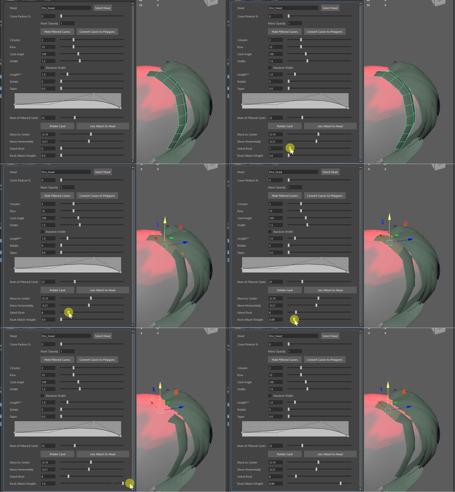
Later, the artists suggested adding a feature to attach only the root of the cards. In response, I introduced a slider to control the number of root faces to attach and adjust the attachment weight.
For this functionality, the first step is to identify the faces at the root of each selected card. When the slider is adjusted, the number of selected root faces increases or decreases accordingly. To achieve this, the current selection of cards needs to be recorded when the slider is pressed to prevent any changes in the target objects during slider adjustments, that’s why there’s a lock_card_selection() called when sliderPressed().
Next, in the face selection function, the first step is to select the faces starting from the root based on the slider value. The second step retrieves the corresponding vertices of the selected faces by cmd.polyInfo(faceToVertex = True) and stores them in another list for further processing.
1
2
3
4
5
6
7
8
9
10
11
12
13
14
15
16
17
18
19
20
21
22
23
24
25
26
27
28
29
30
    def lock_card_selection(self):
        self.sel_cards = cmd.ls(sl = True, type = 'transform')
        curves = cmd.filterExpand(self.sel_cards, sm = 9)
        if curves:
            self.sel_cards = set(self.sel_cards).difference(set(curves))


    def slider_select_faces(self, input):
        if not self.sel_cards:
            cmd.warning('No Cards Selected')
            return
        self.sel_root_level = input

        card_face_dict = {}
        self.sel_root_verts = []
        input = self.clamp(input - 1, 0, 100)
        cmd.select(clear = True)
        for card in self.sel_cards:
            cmd.select(f'{card}.f[0:{input}]', add = True)

        verts = cmd.polyInfo(faceToVertex = True)
        for f in verts:
            v = f.split(":")[1].strip().replace('     ', ',').replace(' ', '')
            vert_list = v.split(',')
            for item in vert_list:
                item = int(item)
                if item not in self.sel_root_verts:
                    self.sel_root_verts.append(item)
        self.sel_root_verts = sorted(self.sel_root_verts)
        self.sel_root_face = cmd.ls(sl = True)
In the second Root Attach Weight slider, two functions are called. The first function records the initial positions of the vertices for the selected root faces, performs a live attach on the root, then captures the deformed vertex positions, then reverting the live attach. The second function live_attach_by_weight handles the actual displacement. It reads the vertex positions before and after deformation, interpolates between them using a linear interpolation (lerp) with the slider input as the factor, and applies the displacement to the vertices using cmd.xform().
1
2
3
4
5
6
7
8
9
10
11
12
13
14
15
16
17
18
19
20
21
22
23
24
25
26
27
28
29
30
31
32
33
34
35
36
37
38
39
40
41
42
43
44
45
46
47
48
49
50
51
52
53
54
55
56
57
58
59
60
61
62
63
64
65
66
67
68
69
70
71
72
73
74
75
    def get_all_verts_pos(self):

        if not self.sel_root_face:
            cmd.warning('No Roots Selected')
            return
        if not self.sel_cards:
            cmd.warning('No Roots Selected')
            return
        if not self.sel_head:
            cmd.warning('No Head Selected')
            return
        cmd.makeLive(self.sel_head)

        self.d1 = {}
        self.d2 = {}
        for card in self.sel_cards:
            vert_pos_bf_dict = {}
            pos_list = []
            card_dp = om.MSelectionList().add(card).getDagPath(0)
            vert_iter = om.MItMeshVertex(card_dp)
            faces_num = cmd.polyEvaluate(card, face = True)
            for item in vert_iter:
                # vert_pos_bf = cmd.xform(f'{card}.f[{i}]', q = True, translation = True)[:3] # only save the first xyz
                mpoint = item.position()
                index = item.index()
                vert_pos_bf = []
                for i in range(3):
                    vert_pos_bf.append(mpoint[i]) #[0,0,0]

                pos_list.append(vert_pos_bf) #[[0,0,0],[1,1,1],[...]]

                vert_pos_bf_dict.update({index:[pos_list[index]]})

            self.d1.update({card:vert_pos_bf_dict})

            cmd.move(0.001, 0, 0, f'{card}.f[0:{faces_num-1}]', relative=True, xformConstraint='live', constrainAlongNormal = True)

            card_dp_af = om.MSelectionList().add(card).getDagPath(0)
            vert_iter_af = om.MItMeshVertex(card_dp_af)
            for item in vert_iter_af:
                mpoint = item.position()
                index = item.index()
                vert_center_af = []
                for i in range(3):
                    vert_center_af.append(mpoint[i])

                self.d1[card][index].append(vert_center_af)

            cmd.undo()
        cmd.makeLive( none=True )


    def live_attach_by_weight(self, input):
        if not self.sel_root_face:
            cmd.warning('No Roots Selected')
            return
        if not self.sel_cards:
            cmd.warning('No Roots Selected')
            return
        if not self.sel_head:
            cmd.warning('No Head Selected')
            return

        self.undo_on('undo root weight')
        input = input/100
        for card in self.d1:
            by_vert = self.d1[card]
            vert_num = len(self.sel_root_verts)
            # for i in range(self.sel_root_level):
            for i in range(vert_num):
                pos_bf = by_vert[i][0]
                pos_af = by_vert[i][1]
                new_pos = self.lerp_vector3(pos_bf, pos_af, input)
                cmd.xform(f'{card}.vtx[{i}]', translation = new_pos)
Undo Chunk Customization
When using a Qt Slider to call a function, there’s a common issue: for example, if Function A moves Sphere B upward by 1.0 each time it’s called, a single slider drag might call the function multiple times, such as moving Sphere B by 50.0. Undoing this with CTRL+Z would then require 50 times to fully revert Sphere B to its original position.
If you want the undo action to revert to the state before dragging the slider, you’ll need to use Maya’s custom Undo Chunk functionality. By wrapping the slider interaction within an undo chunk, all the slider updates during the drag will be treated as a single undoable action, making CTRL+Z efficiently restore the pre-drag state in one step.
In this thread Undo Chunk Solution with QSlider, thanks to user tfox_TD for providing a solution tailored for sliders. The process involves three main steps:
Create a flag initialized in the
__init__function, set toFalseby default.self.in_undo = False- Implement two functions:
undo_on()andundo_off(). These will toggle the flag to True or False respectively.1 2 3 4 5 6 7 8 9 10 11
def undo_on(self, name): if name == 'none': return if not self.in_undo: self.in_undo = True cmd.undoInfo(openChunk=True, chunkName= name) def undo_off(self, name): if self.in_undo: self.in_undo = False cmd.undoInfo(closeChunk=True)
- Connect these functions to the slider’s signals using
sliderPressed.connect(undo_on)andsliderReleased.connect(undo_off). This setup ensures the undo chunk starts when the slider is pressed and ends when released, wrapping the entire drag operation into a single undo action.
p.s. if the actual function is called with sliderMoved or valueChanged, may also need add the undo_on() function into the first line of the called functions.
UV Editor
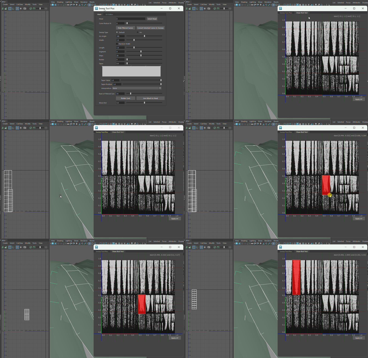
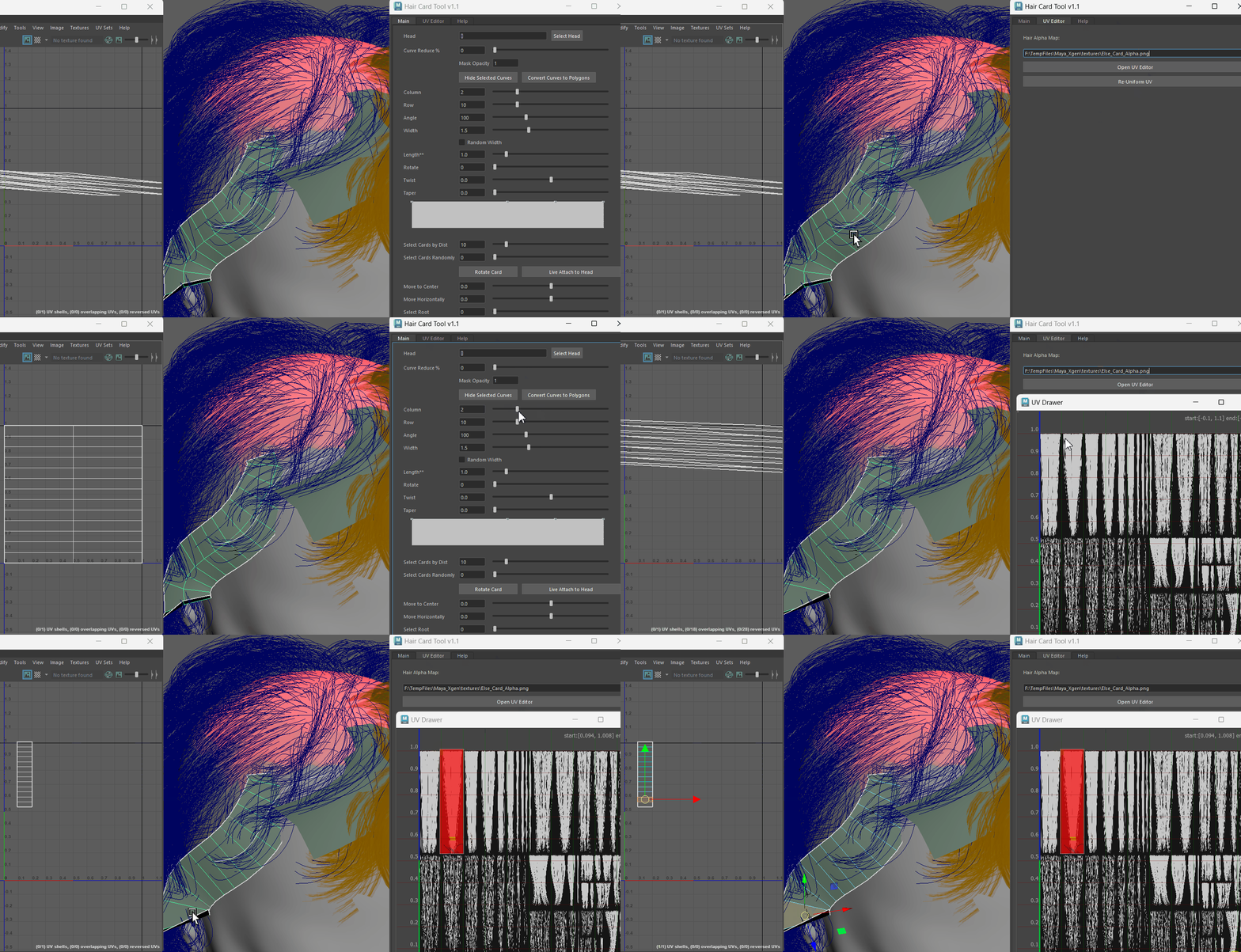
Regarding UVs, I spent some time thinking about what kind of tool could truly speed up the process. I envisioned a system where you could intuitively drag the UV in UV editor directly and have the UVs adjust accordingly. This idea became the foundation for developing this part of the tool.
This part reminded me of creating a snow shader where characters leave imprints on a render target, which are then captured and mapped onto the snow’s rendering. Inspired by this, I considered implementing a 1:1 UV editor panel that could return mouse-click coordinates. These coordinates could then be mapped back into the UV Editor’s layout functionality, enabling precise UV adjustments directly based on user input in a more intuitive way.
QPainter
After some research, I discovered that QPainter can achieve the functionality I need. It allows for custom rendering within a widget.
QPainter also supports events like mousePressEvent, mouseMoveEvent and mouseReleaseEvent, so that can be used for updating the mouse position.
QPainter can also use functions like drawPixmap, drawLine, and drawRect to render the required pixels. Additionally, it allows for customization of the brush color, thickness, and other attributes, giving flexibility in creating the desired visual effects within the editor.
I have separated the entire UV Editor part into a different file, and it has its own window class. Below is the code relates to the actual paintEvent()
1
2
3
4
5
6
7
8
9
10
11
12
13
14
15
16
17
18
19
20
21
22
23
24
25
26
27
28
29
30
31
32
33
34
35
36
37
38
39
40
41
42
43
44
45
46
47
48
49
50
51
52
53
54
55
56
57
58
59
60
61
62
63
64
65
66
67
68
69
70
71
72
73
74
75
76
77
78
79
80
81
82
83
84
85
86
87
88
89
    def paintEvent(self, event):
        painter = QtGui.QPainter()
        painter.begin(self)
        painter.setOpacity(0.7)
        painter.drawPixmap(self.margin, self.margin, self.size, self.size, self.im)
        brush = QtGui.QBrush(QtGui.QColor(255,10,10,255))
        painter.setBrush(brush)
        painter.drawRect(QtCore.QRect(self.begin_pos, self.end_pos))

        # draw y axis
        pen_y_axis = QtGui.QPen(QtGui.QColor(10,10,255,255))
        pen_y_axis.setWidthF(3)
        painter.setPen(pen_y_axis)
        painter.drawLine(self.margin, 0, self.margin,  self.size+200)
        # draw y axis half
        pen_y_axis_half = QtGui.QPen(QtGui.QColor(10,255,10,255))
        pen_y_axis_half.setWidthF(3)
        painter.setPen(pen_y_axis_half)
        painter.drawLine(self.margin, self.margin + self.size/2, self.margin, self.margin + self.size)

        # draw y axis thin and figures
        pen_y_axis_thin = QtGui.QPen(QtGui.QColor(127,0,0,127))
        pen_y_axis_thin.setWidthF(1)
        painter.setPen(pen_y_axis_thin)
        for i in range(11):
            step = self.size/10
            painter.drawLine(0, self.margin + self.size - step*i, self.size + 200, self.margin + self.size - step*i)

        pen_figues = QtGui.QPen(QtGui.QColor(255, 255, 255, 200))
        painter.setPen(pen_figues)
        painter.setFont(QtGui.QFont('Decorative', 8))
        for i in range(11):
            painter.drawText(QtCore.QPoint(self.margin - 20, self.margin + self.size - 5 - step*i), str(i/10))

        # draw x axis
        pen_x_axis = QtGui.QPen(QtGui.QColor(10,10,255,255))
        pen_x_axis.setWidthF(3)
        painter.setPen(pen_x_axis)
        painter.drawLine(0, self.margin + self.size, self.size +  200, self.margin + self.size)

        # draw x axis half
        pen_x_axis_half = QtGui.QPen(QtGui.QColor(255,10,10,255))
        pen_x_axis_half.setWidthF(3)
        painter.setPen(pen_x_axis_half)
        painter.drawLine(self.margin, self.margin + self.size, self.margin + self.size/2, self.margin + self.size)

        # draw x axis thin
        pen_x_axis_thin = QtGui.QPen(QtGui.QColor(0,127,0,127))
        pen_x_axis_thin.setWidthF(1)
        painter.setPen(pen_x_axis_thin)
        for i in range(11):
            step = self.size/10
            painter.drawLine(self.margin + step*i, 0, self.margin+ step*i, self.size + 200)

        painter.drawLine(0, self.margin + self.size, self.size +  200, self.margin + self.size)

        pen_figues = QtGui.QPen(QtGui.QColor(255, 255, 255, 200))
        painter.setPen(pen_figues)
        painter.setFont(QtGui.QFont('Decorative', 8))
        for i in range(11):
            painter.drawText(QtCore.QPoint(self.margin + 5 + step*i, self.margin + self.size + 15), str(i/10))

        # add a HUD figure
        self.output_start_pos_x = (self.begin_pos.x() -  self.margin)/ self.size
        self.output_start_pos_y = 1 - (self.begin_pos.y() -  self.margin)/ self.size

        self.output_end_pos_x =  (self.end_pos.x() - self.margin)/ self.size
        self.output_end_pos_y = (self.end_pos.y() - self.margin)/ self.size
        self.output_end_pos_y = 1.0 - self.output_end_pos_y

        self.draw_pos(painter, f'start:[{self.output_start_pos_x}, {self.output_start_pos_y}] end:[{self.output_end_pos_x}, {self.output_end_pos_y}]')

        painter.end()

    def mousePressEvent(self, event):
        self.begin_pos = event.pos()
        self.end_pos = event.pos()
        self.update()

    def mouseMoveEvent(self, event):
        self.end_pos = event.pos()
        self.update()

    def mouseReleaseEvent(self, event):
        #self.begin_pos = event.pos()
        self.end_pos = event.pos()

        self.update()
UV Reuniform
Initially, my UV batch editor simply allowed translating the entire UV layout to a new position by inputting a layout value. However, during testing, I noticed an issue: if UVs were modified and rows or columns were added to the card afterward, the UVs would distort and broken. To resolve this, I added a “Re-Uniform” function. This function retrieves the row and column count, calculates where the vertices should be positioned, and adjusts the UVs into a 1:1 evenly distributed grid to prevent distortion.
1
2
3
4
5
6
7
8
9
10
11
12
13
14
15
16
17
18
19
    def reuniform_uv(self, card):
        shape = cmd.listRelatives(card)
        creator = cmd.findType(shape, deep=True, type='sweepMeshCreator')[0]
        c = cmd.getAttr(f'{creator}.profileArcSegments')
        r = cmd.getAttr(f'{creator}.interpolationSteps')
        verts_per_row = c + 1
        width = 1.0 / c
        height = 1.0 / r
        pos_0 = [1,1] # top right corner
        pos_list = [pos_0]
        verts_num = cmd.polyEvaluate(card, vertex = True)
        for i in range(1, verts_num):
            pos_x_next = pos_0[0] - width * (i % verts_per_row)
            pos_y_next = pos_0[1] - height * math.floor(i / verts_per_row)
            pos_list.append([pos_x_next, pos_y_next])
            # print(i, pos_x_next, pos_y_next)
            cmd.polyEditUV(f'{card}.vtx[{i}]', relative=False, uValue = pos_x_next, vValue = pos_y_next)
        # print(pos_list)
        cmd.polyEditUV(f'{card}.vtx[0]', relative=False, uValue = pos_0[0], vValue = pos_0[1])
WorkspaceControl
At first, the workspaceControl framework was simple, but after compiling the script into a .pyd file, I encountered an issue where it could not open after being launched once. I wasn’t sure what went wrong, so after researching, I found a very useful workspace control template that helped resolve the problem: Simple_MayaDockingClass.py
This template had one small issue that only appeared after compiling into a .pyd file: when the window is manually closed, attempting to reopen the plugin window throws an “Internal C++ object already deleted” error. 
After investigating, I found that the script tried to delete the instance to prevent duplicate windows, but it couldn’t find the object to delete if the window was already closed manually: 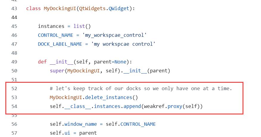
The solution was to add a try-except block to handle the situation: 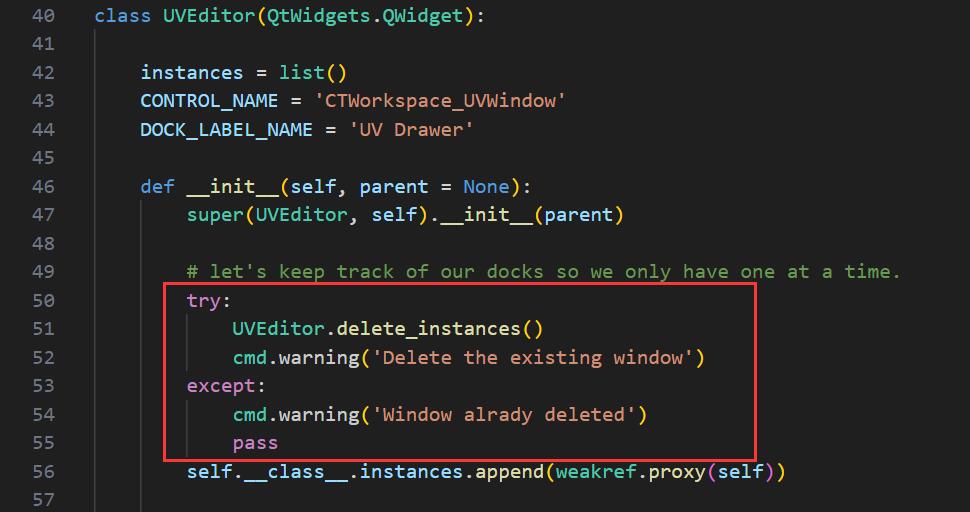
Pyd format Conversion
Generally, when delivering scripts for use, it’s important to prevent accidental modifications that could lead to errors. This is especially true when sending scripts to external teams. In such cases, encrypting the scripts can be helpful. One way to do this is by using Cython to convert Python files into the .pyd format. This format displays as unreadable garbage text when opened, thus protecting the script from being easily modified or understood.
Install Cython
Normally we can use [ maya root path ]\bin\mayapy.exe" setup.py install to install through Cython’s setup.py file that downloaded directly from Cython, but because of my Maya is in C disk and the company pc would warn me that there’s no access to write, so I have to install Cython from Pip and manually setup into Maya Python.
Therefore I run the following command directly in the cmd window. pip install cython pip install setuptools
This will install Cython into the default python folder, for me it is: C:\Users\xxxx\AppData\Local\Programs\Python\Python311
and copy the new added Cython files into Maya Python’s corresponding folder: 
Setup Maya Python folder
There’s also a necessary step in Maya’s Python folder: Create two new folders –> include and libs, under Maya2023/Python, and copy corresponding files into them from the folders that directly under Maya: 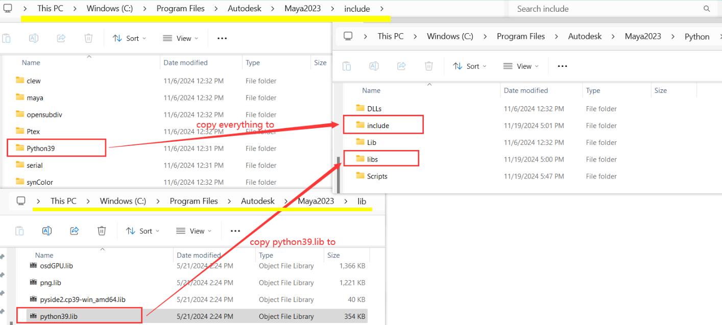
Try import Cython in Maya script Editor, if there’s no error then can move to the compilation.
Cython Compilation
setup.py
Will need a setup.py file that contains the python files that I need to convert into pyd files, and put it into the same folder of my python scripts: 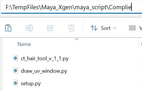
1
2
3
4
5
6
7
8
9
10
11
    # setup.py
    import os
    from distutils.core import setup
    from Cython.Build import cythonize
    from distutils.extension import Extension

    extensions = ['ct_hair_tool_v_1_1.py', 'draw_uv_window.py']

    setup(
        ext_modules = cythonize(extensions)
    )
Run Compilation
Then in cmd window, cd to the folder of the python scripts that I want to convert, and use mayapy.exe to execute the setup.py file by:
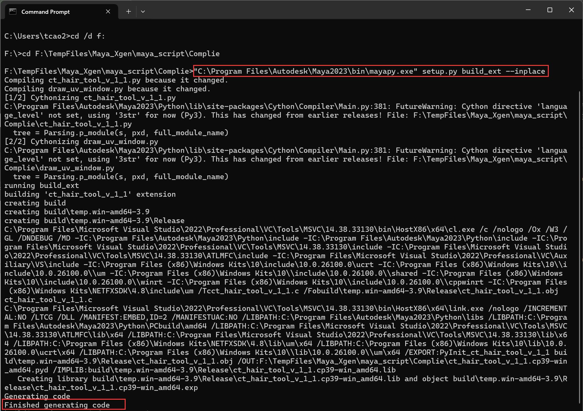
"C:\Program Files\Autodesk\Maya2023\bin\mayapy.exe" setup.py build_ext --inplace
After generation, there’re new files added in the compile folder, then the last step is to remove the suffix generated on the pyd files: 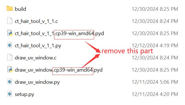
Then we can use those pyd files just like a normal python script, for example:
1
2
3
4
5
6
7
8
    import importlib
    import sys
    sys.path.append(r"F:\TempFiles\Maya_Xgen\maya_script\ToolPack")

    import ct_hair_tool_v_1_1
    importlib.reload(ct_hair_tool_v_1_1)

    my_dock = ct_hair_tool_v_1_1.dock_window(ct_hair_tool_v_1_1.MyDockingUI)
where ct_hair_tool_v_1_1 is ct_hair_tool_v_1_1.pyd
Potential issue
1
2
3
4
    > # Error: DLL load failed: The specified module could not be found.
    > # Traceback (most recent call last):
    > #   File "<maya console>", line 1, in <module>
    > # ImportError: DLL load failed: The specified module could not be found.
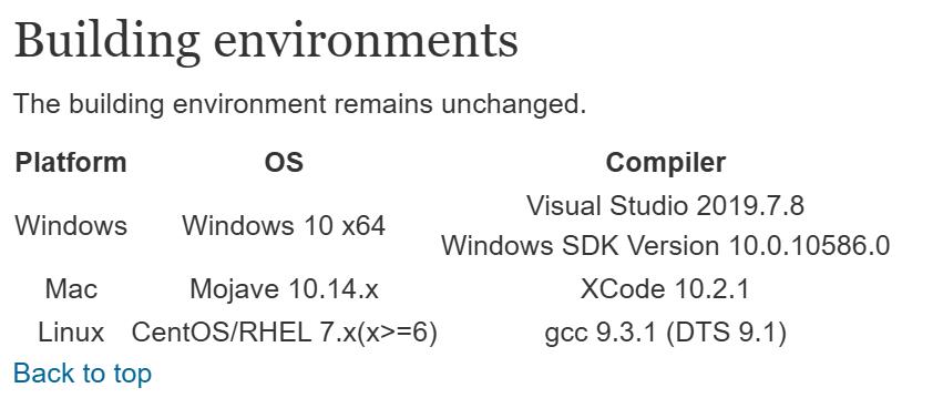
This could be caused by the mismatch of Visual Studio version, so make sure you have the corresponding VS version that Maya needs, you can find it from this Maya’s official site, where development team keeps updating: Around the Corner: Maya 2023 API Update guide Like here, I’m using Maya2023, I need at least Visual Studio 2019. 